12
Suggested Field Testing/Trouble Shooting
1. Run unit in the heating mode (room thermostat calling for heat).
2. Check unit for proper charge.
NOTE: Bands of frost on the condenser coil indicate low refrigerant charge.
3. Shut off power to unit.
4. Disconnect outdoor fan by removing the outdoor fan motor wire from “DF2” on defrost control.
5. Restart unit and allow frost to accumulate.
6. After a few minutes of operation, the unit’s defrost thermostat should close. To verify this, check for 24 volts between “DFT” and
“C” on board. If the temperature at the thermostat is less than 28°F and the thermostat is open, replace the unit’s defrost
thermostat, as it is defective.
7. When the unit’s defrost thermostat has closed, short the test pins on the defrost board until the reversing valve shifts, indicating
defrost. This should take up to 22 seconds depending on what timing period the control is set on. After defrost initiation, the
short must instantly be removed or the unit’s defrost period will only last 3 seconds.
8. The control is shipped from the factory with the compressor delay option selected. This will de-energize the compressor
contactor for 30 seconds on defrost initiation and defrost termination. If the jumper is set to Normal, the compressor will
continue to run during defrost initiation and defrost termination. The control will also ignore the low pressure switch connected
to R-PS1 and PS2 for 5 minutes upon defrost initiation and 5 minutes after defrost termination.
9. After the unit’s defrost thermostat has terminated, check the defrost thermostat for 24 volts between “DFT” and “C”. The reading
should indicate 0 volts (open sensor).
10. Shut off power to unit.
11. Replace outdoor fan motor lead to terminal “DF2” on defrost board and turn on power.
A
IR
FLOW
M
EASUREMENT
AND
A
DJUSTMENT
Please review the
Duct Work
section before proceeding with the airflow measurements and adjustments in this section.
Unit blower curves (see Specification Sheets) are based on external static pressure (ESP per in/W.C.). The duct openings on the
unit are considered internal static pressure. As long as ESP is maintained, the unit will deliver the proper air up to the maximum
static pressure listed for the CFM required by the application (i.e. home, building, etc.)
In general, 400 CFM per ton of cooling capacity is a rule of thumb. Some applications depending on the sensible and latent
capacity requirements may need only 350 CFM or up to 425 CFM per ton. Check condition space load requirements (from load
calculations) and equipment expanded ratings data to match CFM and capacity.
After unit is set and duct work completed, verify the ESP with a 1-inch inclined manometer with pilot tubes or a Magnahelic gauge
and confirm CFM to blower curves in the Specification Sheets.
NOTE:
Never run CFM below 350 CFM per ton, evaporator freezing or poor unit performance is possible.
A
IR
F
LOW
A
DJUSTMENTS
F
OR
I
NDOOR
B
LOWER
M
OTOR
ECM Motor
The ECM control board is factory set with the dip switch #4 in the “ON” position for single stage units and to the "OFF" position for
the 2 stage units. All other dip switches are factory set in the “OFF” position.
For most applications, the settings are to be changed
according to the electric heat size.
The ECM motor provides many features not available on the traditional PSC motor. These features include:
•
Improved Efficiency
•
Constant CFM
•
Soft Start and Stop
•
Improved Humidity Control
ECM Motor Speed Adjustment
Each ECM blower motor has been preprogrammed for operation at 4 distinct air flow levels when operating in Cooling/Heat Pump
mode or Electric Heat mode. These 4 distinct levels may also be adjusted slightly lower or higher if desired. The adjustment
between levels and the trim adjustments are made by changing the dip switch(s) either to an "OFF" or "ON" position.
See Appendix for Blower Performance Data tables.
APH D
IP
S
WITCH
F
UNCTIONS
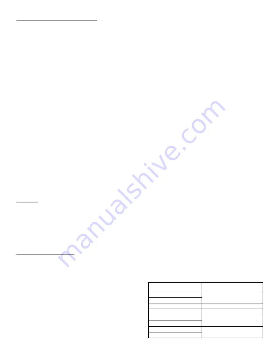
The ECM motor has an electronic control that contains eight (8) 2-
position dip switches. The function of these dip switches is shown
in
Table 1.
APH CFM D
ELIVERY
AND
A
DJUSTMENTS
See Appendix for CFM Output, Adjustments and DIP switch
settings.
APH T
HERMOSTAT
“F
AN
O
NLY
” M
ODE
During Fan Only Operations, the CFM output is 50% of the high stage
cooling setting.
DIP SWITCH NUMBER
FUNCTION
1
2
3
N/A
4
Indoor Thermostat
5
6
7
8
Cooling & Heat Pump CFM
CFM Trim Adjust
Elect ric Heat
Table 1
Содержание APG1624060M41
Страница 16: ...16 APPENDIX...
Страница 23: ...23 THIS PAGE LEFT INTENTIONALLYBLANK...


