ALUZ A1-ZIBI-PVT-RGBW Скачать руководство пользователя страница 11

Installation Instructions

1170 N Red Gum St, Anaheim, CA 92806

©  ALUZ All Rights Reserved. ALUZ reserves the right to make changes or withdraw specifi cations without prior notice.

[email protected]

aluz.lighting

866.ALUZ.LTG | 714.535.7900

A1 Series 

|


Surface

ZIBI


Pivot RGBW

(A1-ZIBI-PVT-RGBW)

Page 11 of 11

4 / 29 / 2022 / Rev 2

Troubleshooting & Continuity Test

1

2

3

4

5

Red Probe

Black Probe

1

2

3

4

5

Red Probe

Black Probe

1

2

3

4

5

Red Probe

Black Probe

Frayed End

Metal Flakes

Foreign Object

Damaged Lightstrip

Torn Lightstrip

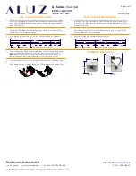
TROUBLESHOOTING TIPS

• Do not reset the breaker multiple times.

• If the unit is overloaded, the breaker will trip, shutting off the driver and lights.

•  If the breaker reset button has been held down by hand or any type of pressure, 

such as duct tape, or if the breaker has been reset multiple times without 

troubleshooting, the unit will:

   - Burn the driver bobbin.

   - Burn the thermal or magnetic breaker.

   - Burn the driver lead wires due to high amperage caused by overload.

   - Short circuit in line which will not allow the breaker to reset.

   - Damage the lighting.

CONTINUITY TEST

A continuity test is performed to determine if electricity can pass through

two points on an electrical circuit. This helps identify shorts or malfunctions

in the luminaire. Use a multimeter or continuity tester to perform the steps below. 

• Always perform a continuity test before connecting to power source.

• Malfunctions are not always as obvious as the lights not turning on. 

•  A short or malfunction in the line or luminaire will cause damage over time, 

irreparably damaging the lighting and voiding warranty.

1

2

3

Measure area where luminaire will be installed. Use a laser line to create 

a reference line along installation area, ensuring consistent alignment 

of mounting channels. Mark location where mounting channels will be 

installed along reference line.

2

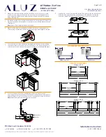
Check for metal particles or other foreign objects causing the short.

3

Check to make sure cuts in the lightstrip are clean and not frayed, causing 

positive and negative copper pads to touch.

1

Turn off power before beginning. Verify power is off by using a non-contact 

circuit tester (by others). Touch the probe of the tester to the positive wire of 

the power source. The tester will light up if an electrical current is detected.

2

Setup your multimeter tester (by others). First, insert the black probe lead 

into the COM jack, then insert the red probe lead into the V

 jack.

1

Turn off power before beginning. Check for any twisting or damage to the 

circuit in the LED lightstrip. If there is excessive damage and the circuit is 

broken, the lightstrip must be replaced.

4

Touch the red probe to the luminaire extrusion and the black probe to the 

ground wire (green). If the luminaire is properly grounded, the multimeter 

will beep, flash, or read 0

 (ohms). If there is no conductive path, the 

multimeter will not show any feedback. Troubleshoot to identify the 

malfunction in the ground wire.

5

Touch the red probe to any wire and the black probe to each other wire. 

Repeat process for each wire. If a conductive path is formed between any of 

the wires, the multimeter will beep, flash, or read 0

 (ohms). Troubleshoot 

to identify the malfunction in the line. If there is no conductive path, the 

multimeter will not show any feedback.

Example: 

Check for continuity between Wire 2 and Wire 4

6

Touch the red probe to the luminaire housing and the black probe to each 

wire except ground. If a conductive path is formed between the housing 

and any of the wires, the multimeter will beep, flash, or read 0

 (ohms). 

Troubleshoot to identify the malfunction in the line. If there is no conductive 

path, the multimeter will not show any feedback.

7

Set multimeter to AC voltage and test power source. Confi rm the correct 

voltage before connecting luminaire to power source. If the voltage reading 

is more than 1 volt greater than the marked output voltage, there is a 

problem with the power source or driver.

8

Connect luminaire to power source. If LEDs do not turn on, troubleshoot to 

fi nd the problem in the line.

Содержание A1-ZIBI-PVT-RGBW

Страница 1: ...e Integral Driver or Low Voltage Remote Driver Color changing LEDs Available in 3 Watts up to 18 Watts Per Foot Product is shipped in 1 2 3 and 4 luminaires Available for outdoor rated installations Electric Hammer Drill 14 4 to 28 Volt Cordless Drill Phillips Bits Utility Knife Electrical Cord Marker Wire Stripper Long Nose Pliers Drill Bits Concrete or Wood Electrical Three Ways Safety Glasses M...

Страница 2: ...e mounting clips section for details Do not install mounting clips on uneven surfaces Use shims to level out height of mounting clips if necessary Do not install mounting clips after luminaires have been assembled Install mounting clips first then install luminaire into mounting clips Do not force luminaire into a space that is too small Do not force luminaire with cord grip into soffit Fig 3 Do not...

Страница 3: ...to mounting clips Install set screws to each mounting clip if applicable Set screws are required for downward facing outward facing and vertically mounted applications 3 Use a mounting clip at the junction between two luminaire segments Example 20 Run 4 Lay mounting clips along reference line and pre drill using an appropriate drill bit for surface material and screw size Typical screw size is 8 3...

Страница 4: ...weight of the luminaires 2 Use 1 mounting clip every 2 rounded up Use a minimum of 2 mounting clips per luminaire segment For vertical applications create a stopper at the bottom of the run to prevent sliding 1 Measure area where luminaire will be installed Use a laser line to create a reference line along installation area ensuring consistent alignment of mounting clips Mark location where each m...

Страница 5: ...ing Continuity Test page for additional information 7 Verify wiring diagram then connect luminaire to power source 2 The number of required mounting clips differs for dry and wet location products Verify number of mounting clips is appropriate for installation environment before beginning installation Do not install luminaires with inadequate number of mounting clips Refer to the Mounting Clips pa...

Страница 6: ... can move freely Turn the mounting plate until desired angle is achieved then mate the locking bump with locking hole Tighten set screw until mounting plate is secured in place Note Refer to Angle Increments diagram next page 2 Determine number of mounting arms needed Use a minimum of 2 mounting arms per luminaire Mount arms 6 from center of mounting plate to the end of luminaire Note Refer to Spa...

Страница 7: ... can move freely Turn the mounting plate until desired angle is achieved then mate the locking bump with locking hole Tighten set screw until mounting plate is secured in place Note Refer to Angle Increments diagram next page 2 Determine number of mounting arms needed Use a minimum of 2 mounting arms per luminaire Mount arms 6 from center of mounting plate to the end of luminaire Note Refer to Spa...

Страница 8: ... from Wall Set Screw Shrink Tube Apply Heat 2 1 Determine number of louvers needed Louvers are available in 1 increments Specify total length of reflectors needed 4 If applicable connect disconnects between luminaires Slide shrink tube over connectors and apply heat The shrink tube will shrink down sealing the connectors Apply silicone around sealed connectors for a stronger seal 5 Mount luminaire...

Страница 9: ...r Set Screw Shrink Tube Apply Heat 2 1 Determine number of reflectors needed Reflectors are available in 1 2 3 or 4 increments Specify total length of reflectors needed 4 If applicable connect disconnects between luminaires Slide shrink tube over connectors and apply heat The shrink tube will shrink down sealing the connectors Apply silicone around sealed connectors for a stronger seal 5 Mount lum...

Страница 10: ...the Pivot Function Turn knob to tighten Upper Extrusion Lower Extrusion Pivot Lock Bar Pivot Lock Knob Turn knob to loosen 1 Slightly unscrew Pivot Lock Knobs on both ends of luminaire until Pivot Lock Bar and Upper Extrusion are able to move freely Do not remove Pivot Lock Knob DIAGRAM OF ASSEMBLY 2 Adjust angle as desired Tip Use an angle finder or sliding bevel to ensure accuracy of angles 3 Tur...

Страница 11: ...hort 3 Check to make sure cuts in the lightstrip are clean and not frayed causing positive and negative copper pads to touch 1 Turn off power before beginning Verify power is off by using a non contact circuit tester by others Touch the probe of the tester to the positive wire of the power source The tester will light up if an electrical current is detected 2 Setup your multimeter tester by others...

Отзывы: