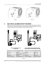
background image

09.2019 

www.alutech-group.com

Assembly and operation manual

Targo

 drives for industrial doors 

(TR-3531-230E / TR-5020-230E / TR-5024-230E / TR-5013-400E / TR-5020-400E / 
TR-5024-400E / TR-10024-400E / TR-13018-400E / TR-13012-400E)

English

Montage- und Betriebsanleitung

Antriebe 

Targo

 für Industrietore

(TR-3531-230E / TR-5020-230E / TR-5024-230E / TR-5013-400E / TR-5020-400E / 
TR-5024-400E / TR-10024-400E / TR-13018-400E / TR-13012-400E)

Deutsch

Manuel d’installation et d’utilisation

Commandes 

Targo

 pour les portes industrielles 

( TR-3531-230E / TR-5020-230E / TR-5024-230E / TR-5013-400E / TR-5020-400E / 
TR-5024-400E / TR-10024-400E / TR-13018-400E / TR-13012-400E )

Français

Содержание Targo TR-10024-400E

Страница 1: ...E English Montage und Betriebsanleitung Antriebe Targo für Industrietore TR 3531 230E TR 5020 230E TR 5024 230E TR 5013 400E TR 5020 400E TR 5024 400E TR 10024 400E TR 13018 400E TR 13012 400E Deutsch Manuel d installation et d utilisation Commandes Targo pour les portes industrielles TR 3531 230E TR 5020 230E TR 5024 230E TR 5013 400E TR 5020 400E TR 5024 400E TR 10024 400E TR 13018 400E TR 13012...

Страница 2: ......

Страница 3: ... Mounting the drive on the door shaft 6 4 2 Emergency manual control using chain operation 8 4 3 Manual release 9 5 ELECTRICAL CONNECTION OF THE DRIVE 10 6 ADJUSTMENT OF FINAL POSITIONS 11 7 TESTING AND COMMISSIONING 11 8 OPERATION 12 9 TROUBLESHOOTING 13 10 STORAGE TRANSPORTATION AND DISPOSAL 13 11 WARRANTY OBLIGATIONS 13 12 COMMISSIONING CERTIFICATE 14 13 INFORMATION ON REPAIRS DURING WARRANTY P...

Страница 4: ...hen performing any works mounting repair maintenance cleaning etc and connections inside the drive disconnect the mains circuit If the master switch or similar device is out of sight then attach a safety sign stating Do not turn on People are working and take measures preventing the possibility of accidental restoring of the power supply The company reserves the right to introduce changes in this ...

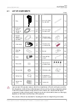
Страница 5: ...Plain washer 4 pcs 17 Instructions for extension cords 1 pc 8 Spring washer 4 pcs 18 Information plate 1 pc 9 Locking ring 2 pcs 19 Assembly and operation manual 1 pc 10 Locking ring screw 2 pcs 20 Control unit 1 pc Y Y Upon receipt of the product please check the completeness of the kit and make sure all the kit components are free of any visible damage In the case of any missing components pleas...

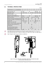
Страница 6: ...tion at rated load torque A 3 3 3 1 1 2 Gear box ratio 48 1 70 1 58 1 70 1 58 1 80 1 Maximum use intensity ED 25 S3 60 S3 Maximum time of continuous operation min 10 15 Thermal protection of electric motor ºС 120 Protection class I Drive housing protection degree IP65 Operating temperature range ºС 20 50 Drive weight with chain and cables kg 16 5 16 14 19 Y Y All specified technical specifications...

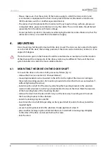
Страница 7: ...ng in that the space around the drive ensures easy and safe manual release Please make sure that the drive and its components are at a sufficient distance from any heat source or open fire The violation of this requirement can result in the damage of the product cause its malfunctioning cause fire or other dangerous situations Please make sure that the surface of the drive system and its installat...

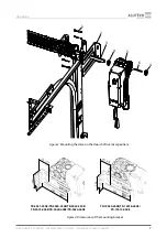
Страница 8: ...and the components of the drive system may be different The task of the drive system installer is to select the most suitable solution 4 1 MOUNTING THE DRIVE ON THE DOOR SHAFT To mount the drive on the door shaft proceed as follows fig 3 release the drive see section 4 3 Manual release mounting bracket 2 can be mounted to the left or to the right of the drive According to the selected working posi...

Страница 9: ...SÉRIE TR 7 Mounting 1 2 4 5 6 3 4 Figure 3 Mounting the drive on the door shaft vertical position 150 TR 3531 230E TR 5020 230E TR 5024 230E TR 5013 400E TR 5020 400E TR 5024 400E TR 10024 400E TR 13018 400E TR 13012 400E Figure 4 Dimensions of the mounting bracket ...

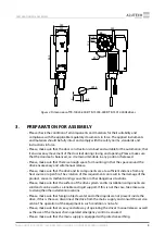
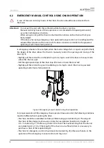
Страница 10: ...ening and closing of the door fig 5 Slightly pull the cord with a red handle 1 up to its stop to switch the drive to manual mode where the chain is used Pull the appropriate drop of the chain loop 2 to raise or lower the door leaf Slightly pull the cord with a green handle 3 up to its stop to return the drive to powered operating mode mains fed operation 1 2 3 Figure 5 Emergency manual control usi...

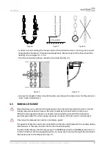
Страница 11: ...estricted to trained personnel only and only when the door is closed During manual mechanical release the drive should be disconnected from the mains When the drive gearbox release is activated uncontrolled movement of the door leaf is possible especially if the door springs are weak or broken if the door leaf is not balanced Y Y Only move the released door leaf at a moderate speed The gearbox of ...

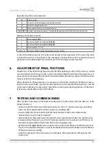
Страница 12: ...e control unit NC S1 S2 M 1 L1 COM L2 L1 L2 N BK BU BN YE GN NC 2 87 6543 1 ENCODER S3 S3 M 3 L1 L2 L3 L1 L2 L3 BK BU BN YE GN NC S1 S2 NC 2 87 654 3 1 ENCODER TR 3531 230E TR 5020 230E TR 5024 230E TR 5013 400E TR 5020 400E TR 5024 400E TR 10024 400E TR 13018 400E TR 13012 400E COLOUR MARKING OF WIRES OF ELECTRIC MOTOR CABLE DESCRIPTION COLOUR MARKING OF WIRES OF ELECTRIC MOTOR CABLE DESCRIPTION ...

Страница 13: ...ition by means of the drive chain reducer or by the drive releasing After adjustment of final positions it is necessary to check the movement of the door leaf us ing the control unit Make sure that the door leaf stops at the required final positions and the control unit indication corresponds to the extreme closing and opening positions of the doors If necessary adjust the position of the doors 7 ...

Страница 14: ... the manual release facility to disengage the door s drive as an open door can fall quickly due to slack or broken springs or door imbalance Regularly check the drive system check cables springs and mounting hardware for the signs of wear damage or imbalance It is prohibited to use a door which requires repair or adjustment as the mounting defect or incorrect balance of the door may result in inju...

Страница 15: ...oduct shall be stored in its packaging in closed dry spaces Do not expose to atmospheric precipitation or direct sunlight Shelf life is 3 years from the manufacture date Transportation can be performed using all types of covered ground vehicles fitted with measures to prevent shock and movement inside the vehicle Disposal of the product shall comply with the regulatory and legal requirements on re...

Страница 16: ... Serial number and production date data from the product label Information on the organisation authorised to perform mounting and maintenance name address phone Installation date day month year LS Signature of the person in charge of installation _____________ ____________________ signature full name The consumer Client has checked the content of the set is informed on and agrees with the warranty...

Страница 17: ...Signature of the person in charge of repair____________ __________________________ signature full name 14 STATEMENT OF COMPLIANCE Copies of declarations of conformity for products can be found at http www alutech group com en products other automatics documents Importer to the Republic of Belarus Authorised representative ALUTECH Systems s r o 348 02 Czech Republic Bor u Tachova CTPark Bor Nova Ho...

Страница 18: ......

Страница 19: ...ONTAGE 22 4 1 Montage an der Torwelle 22 4 2 Manuelle Notfallsteuerung mittels Kette 24 4 3 Manuelle Entriegelung 25 5 ELEKTRISCHE ANSCHLÜSSE 26 6 EINSTELLUNG DER ENDLAGEN 27 7 BETRIEBSÜBERPRÜFUNG UND INBETRIEBNAHME 27 8 BEDIENUNG 28 9 STÖRUNGEN UND STÖRUNGSBEHEBUNG 29 10 LAGERUNG TRANSPORT UND ENTSORGUNG 29 11 GARANTIEBEDINGUNGEN 29 12 INBETRIEBNAHMEBESCHEINIGUNG 30 13 ANGABEN ÜBER REPARATUREN WÄ...

Страница 20: ...cht sind Die Anlage ist nicht für den Betrieb in einem sauren salzigen oder explosionsgefährdeten Milieu ausgelegt Vor elektrischen Arbeiten Montage Reparaturen Wartung Reinigen und Anschlüssen im Ge rät ist die Anlage spannungsfrei zu schalten Falls der Hauptschalter außer Sicht ist bringen Sie das Schild Nicht einschalten Es wird gearbeitet an und treffen Sie die Maßnahmen gegen unbefugtes Wiede...

Страница 21: ...sshlüs sel für die Klauen 1 St 7 Karosserie scheibe 4 St 17 Anleitung für die Verlängerungs seile 1 St 8 Federscheibe 4 St 18 Typenschild 1 St 9 Sicherungsring 2 St 19 Montage und Betriebsanleitung 1 St 10 Sicherungs schraube 2 St 20 Steuergerät 1 St Y Y Nach Erhalt des Produktes ist sofort auf Vollständigkeit und Unversehrtheit zu prüfen Bei Reklamationen ist der Hersteller unverzüglich zu inform...

Страница 22: ...riebeuntersetzung 48 1 70 1 58 1 70 1 58 1 80 1 Maximale Nutzungsintensität ED 25 S3 60 S3 Maximale Dauerbetriebszeit min 10 15 Thermoschutz des Elektromotors ºС 120 Schutzklasse I Schutzart IP65 Betriebstemperaturbereich ºС 20 50 Gewicht des Antriebes mit Kette und Kabeln kg 16 5 16 14 19 Y Y Alle angegeben technischen Daten sind bei der Umgebungstemperatur 20 ºС 5 ºС gültig Schalldruckpegel des ...

Страница 23: ...anuelle Entriegelung ermöglicht Stellen Sie sicher dass der Antrieb und all seine Elemente ausreichend weit von der Wärmequelle und der offenen Flamme entfernt sind Andernfalls kann es zu Beschädigungen des Produktes Fehlfunktionen Bränden oder anderen gefährlichen Situationen führen Stellen Sie sicher dass die Oberflächen des Montageortes des Antriebssystems und seiner Komponenten widerstandsfähi...

Страница 24: ...t den richtigen Einbauort des Antriebssystems 4 1 MONTAGE AN DER TORWELLE Zur Montage des Antriebs an der Torwelle ist wie folgt vorzugehen Abb 3 Entriegeln Sie den Antrieb siehe Kap 4 3 Manuelle Entriegelung Der Montagewinkel 2 kann auf der linken oder rechten Seite des Antriebes montiert werden Befestigen Sie den Montagewinkel 2 am Antrieb 5 mittels der Schrauben 1 mit den Scheiben entsprechend ...

Страница 25: ...IE TR 23 MONTAGE 1 2 4 5 6 3 4 Abbildung 3 Montage des Antriebes an der Torwelle senkrechte Position 150 TR 3531 230E TR 5020 230E TR 5024 230E TR 5013 400E TR 5020 400E TR 5024 400E TR 10024 400E TR 13018 400E TR 13012 400E Abbildung 4 Abmessungen des Montagewinkels ...

Страница 26: ...on Hand zu öffnen und zu schließen Abb 5 Für die manuelle Steuerung mittels Kette ziehen Sie den roten Hebel nach unten bis zum Anschlag Ziehen Sie die erforderliche Kette zum Heben oder Senken des Torblattes Ziehen Sie nach der Verwendung der Kette den grünen Hebel nach unten bis zum Anschlag um den Betrieb des Antriebes wiederherzustellen Netzbetrieb 1 2 3 Abbildung 5 Manuelle Notfallsteuerung m...

Страница 27: ...ornehmen und zwar nur bei geschlossenem Tor Bei Verwendung der manuellen mechanischen Entriegelung muss der Antrieb vom Stromnetz getrennt werden Bei der Entriegelung des Antriebsgetriebes kann sich das Torblatt in unkontrolliert bewegen wenn die Feder abgespannt oder zerbrochen sind dasTorblatt nicht ausgewuchtet ist Y Y Wenn das Tor entriegelt ist kann das Tor nur mit mäßiger Geschwindigkeit bet...

Страница 28: ...rden NC S1 S2 M 1 L1 COM L2 L1 L2 N BK BU BN YE GN NC 2 87 6543 1 ENCODER S3 S3 M 3 L1 L2 L3 L1 L2 L3 BK BU BN YE GN NC S1 S2 NC 2 87 654 3 1 ENCODER TR 3531 230E TR 5020 230E TR 5024 230E TR 5013 400E TR 5020 400E TR 5024 400E TR 10024 400E TR 13018 400E TR 13012 400E FARBKENNZEICHNUNG VON LEITUNGEN DER MOTORKABEL BESCHREIBUNG FARBKENNZEICHNUNG VON LEITUNGEN DER MOTORKABEL BESCHREIBUNG BK schwarz...

Страница 29: ...egelung des Antriebes in die Zwischenstellung gebracht werden Nach der Einstellung der Endlagen muss die Bewegung desTorblattes mit dem Steuergerät überprüft werden Stellen Sie sicher dass das Torblatt in den benötigten Endlagen stehen bleibt und die Anzeige des Steuergerätes den Endlagen der Schließ und Öffnungsbe wegungen des Tores entspricht 7 BETRIEBSÜBERPRÜFUNG UND INBETRIEBNAHME Nach Montage...

Страница 30: ...Torfahrt ist verboten Kinder nicht mit Steuerungselementen spielen lassen Handsender außer Reichweite von Kindern anbringen Bei der manuellen Entriegelung vorsichtig sein da das geöffneteTor wegen Lockerung Federbruch oder Gleichgewichtsstörung abstürzen kann Regelmäßig das Antriebssystem u a Leitungen Federn und Montagearmierung auf Abnutzungserscheinungen Schäden und Federausgleich Störungen übe...

Страница 31: ...n Endlagen sind nicht eingestellt oder nicht korrekt Stellen Sie die Endlagen des Tores ein Der Antrieb funktioniert auf einmal nicht wenn das Tor noch läuft Thermoschutz von Antrieb spricht an Lassen Sie den Antrieb kühlen Y Y Im Störungsfall der mithilfe der Informationen aus dieser Anleitung nicht beheben werden kann wird es empfohlen ein Serviceunternehmen zu kontaktieren Für mehr Informatione...

Страница 32: ...en des Wassers auftreten bei den Umständen höherer Gewalt Brand Gewitterschlag Hochwasser Erdbeben und andere Naturkatastrophen bei Schäden die durch Auftraggeber oder Dritte verursacht sind bei Fehlern und Störungen die durch ausfallende optische Prüfung und Wartung bedingt sind beim Fehlen der ausgefüllten Anleitung Informationen über Servicestellen finden Sie unter http www alutech group com fe...

Страница 33: ...Angaben über Serviceorganisation Verzeichnis von Reparaturarbeiten Reparaturdatum Tag Monat Jahr Stempel Unterschrift des Verantwortlichen für die Reparatur Unterschrift Name des Unterzeichners 14 ZERTIFIKATE Kopien der Konformitätserklärungen finden Sie unter http www alutech group com product other auto DOCUMENTS Importeur in der Republik Belarus bevollmächtigter Vertreter des Herstellers ALUTEC...

Страница 34: ......

Страница 35: ...on de la commande sur l arbre de la porte 38 18 2 Commande manuelle de secours avec l utilisation d une chaîne 40 18 3 Déverrouillage manuel 41 19 BRANCHEMENTS ÉLECTRIQUES 42 20 RÉGLAGE DES POSITIONS FINALES 43 21 VÉRIFICATION ET MISE EN SERVICE 43 22 UTILISATION 44 23 ANOMALIES DE FONCTIONNEMENT ET LES RECOMMANDATIONS DE LEUR RÉPARATION 45 24 STOCKAGE TRANSPORT ET RECYCLAGE 45 25 OBLIGATIONS DE G...

Страница 36: ...e utilisation en milieu corrosif salin ou dans des endroits à risques d explosion Pendant les travaux installation réparation entretien nettoyage et les branchements à l in térieur de la commande débranchez le circuit d alimentation Si le commutateur est hors de la zone de visibilité il est nécessaire de fixer un panneau Ne pas brancher le courant Les gens travaillent et prenez toutes les précauti...

Страница 37: ...delle plate 4 pcs 17 Mode d emploi des rallonges 1 pcs 8 Rondelle à resort 4 pcs 18 Plaque de renseignements 1 pcs 9 Bague de verrouillage 2 pcs 19 Manuel d installation et d utilisation 1 pcs 10 Vis de la bague de verrouillage 2 pcs 20 Dispositif de commande 1 pcs Y Y Après avoir reçu le produit assurez vous que le kit soit complet et que ses composants n ont subi aucun dommage visible En cas de ...

Страница 38: ...t réducteur 48 1 70 1 58 1 70 1 58 1 80 1 Intensité d utilisation max ED 25 S3 60 S3 Durée de fonctionnement en continu max min 10 15 Protection thermique du moteur électrique ºС 120 Catégorie de protection I Indice de protection du boîtier du moteur IP65 Plage de températures ºС 20 50 Poids du moteur avec chaîne et câbles kg 16 5 16 14 19 Y Y Toutes les caractéristiques citées ci dessus sont vala...

Страница 39: ...reste immobile dans n importe quelle position Assurez vous qu il y ait assez de place pour l installation car l espace autour de la commande permet un déverrouillage manuel facile et sûr Assurez vous que la commande et ses composants soient suffisamment éloignés de toute source de chaleur et de flammes Ne pas respecter cette exigence peut entraîner un sérieux dommage du produit provoquer un foncti...

Страница 40: ...nstallation de la commande et des composants du système de commande peut être différent C est le technicien de l installation du système de commande qui a pour tâche de choisir la solution la mieux adaptée 4 1 INSTALLATION DE LA COMMANDE SUR L ARBRE DE LA PORTE Pour effectuer l installation de la commande sur l arbre de la porte procédez comme suit Fig 3 Déverrouillez la commande voir paragraphe 4...

Страница 41: ...9 INSTALLATION 1 2 4 5 6 3 4 Figure 3 Installation de la commande sur l arbre de la porte position verticale 150 TR 3531 230E TR 5020 230E TR 5024 230E TR 5013 400E TR 5020 400E TR 5024 400E TR 10024 400E TR 13018 400E TR 13012 400E Figure 4 Dimensions du support de montage ...

Страница 42: ...ntrôler manuellement l ouverture et la fermeture du portail par le moyen de la chaîne Fig 5 Tirez doucement la rallonge avec la poignée rouge jusqu au bout pour mettre la commande en mode manuel par chaîne Tirez le fil de chaîne approprié pour relever ou abaisser le tablier de la porte Après avoir utilisé la chaîne tirez doucement le cordon avec la poignée verte jusqu au bout pour revenir au mode ...

Страница 43: ...les poignées 4 3 DÉVERROUILLAGE MANUEL Y Y Le déverrouillage n est autorisé que pour le personnel qualifié et uniquement lorsque les portes sont fermées Lors de l utilisation du déverrouillage manuel mécanique la commande doit être débranchée du réseau électrique Lorsque le réducteur est déverrouillé des mouvements incontrôlés du tablier de la porte peuvent se produire si les ressorts de la porte ...

Страница 44: ... commande Fig 13 Les câbles électriques de la commande doivent être raccordés au bloc de commande externe conformément au mode d emploi du bloc de commande NC S1 S2 M 1 L1 COM L2 L1 L2 N BK BU BN YE GN NC 2 87 6543 1 ENCODER S3 S3 M 3 L1 L2 L3 L1 L2 L3 BK BU BN YE GN NC S1 S2 NC 2 87 654 3 1 ENCODER TR 3531 230E TR 5020 230E TR 5024 230E TR 5013 400E TR 5020 400E TR 5024 400E TR 10024 400E TR 1301...

Страница 45: ...de Après avoir réglé les positions finales il y a lieu de contrôler le mouvement du tablier de la porte à l aide du bloc de commande Assurez vous que le tablier de la porte s arrête dans les positions fi nales requises tandis que l indication affichée sur le bloc de commande correspond aux positions extrêmes de fermeture et d ouverture de la porte Si nécessaire ajustez la position de la porte 7 VÉ...

Страница 46: ...s lorsque les portes se déplacent Ne permettez pas aux enfants de jouer avec les télécommandes Placez les commandes hors de la portée des enfants Soyez prudent lorsque vous utilisez le déblocage manuel de la porte puisque la porte ouverte peut tomber rapidement en raison d un affaiblissement ou d une panne de ressorts ou d un déséquilibre Vérifiez le système de commande régulièrement en particulie...

Страница 47: ...de la commande est incorrect Supprimez l obstacle au mouvement de la porte vérifiez le réglage de positions finales La porte de s arrête pas dans les positions finales requises Les positions finales ne sont pas réglées ou elles sont déréglées Réglez les positions finales de la porte Lorsque la porte est en mouvement la commande s arrête brusquement La protection thermique du moteur de la commande ...

Страница 48: ...ntie Note les pièces remplacées au titre e la garantie deviennent la propriété du service qui effectue la réparation du produit La garantie ne s applique pas dans les cas suivants non respect des règles de stockage de transport d exploitation et d installation du produit installation ajustage réparation réinstallation ou modification du produit par les personnes non autorisées à effectuer ce genre...

Страница 49: ...sable de l installation signature Nom complet Le consommateur Client a vérifié l intégralité du produit il a étudié les conditions et les pé riodes de garantie et les accepte il n a pas de réserves à déclarer sur l apparence du produit Le produit est installé et configuré conformément aux exigences en vigueur et reconnu apte à l utilisation Le consommateur est informé sur les dangers et les risque...

Страница 50: ... Renseignements sur la société agrée pour les réparations Liste des réparations Date des réparations Date mois année L S Signature du responsable des réparations signature Nom complet Unterschrift Name des Unterzeichners 14 CERTIFICATS Les copies des déclarations de conformité sont disponibles à l adresse suivante http www alutech group com product other auto DOCUMENTS Importateur en République du...

Страница 51: ......

Страница 52: ...0 11 01 www alutech group com ALUTECH Doors Systems LLC Selitskogo Straße 10 220075 Minsk Republik Belarus Tel 375 17 330 11 00 Fax 375 17 330 11 01 www alutech group com Sarl ALUTECH Door systems 10 rue Selitskogo 220075 Minsk République du Bélarus Tel 375 17 330 11 00 Fax 375 17 330 11 01 www alutech group com ...

Отзывы: