background image

LEVIGATO DRIVES (LG SERIES) 

|

 LEVIGATO ANTRIEBE (SERIE LG) 

|

 COMMANDES LEVIGATO (SERIE LG)

66

DESCRIPTION DU PRODUIT

•  n’endommagez pas le cordon ; 
•  ne le tordez pas, ne le pliez pas trop et ne l’étirez pas ; 
•  ne placez pas d’objets lourds sur le cordon et ne le placez pas près d’objets chauds ; 
•  assurez un accès facile à la prise ; 
•  n’utilisez que le cordon fourni dans l’ensemble complet ; 
•  il est interdit d’utiliser un cordon endommagé ou défectueux. Si le cordon est endommagé, 

il doit être remplacé par un spécialiste du fabricant ou un technicien de service.

Lors de l’utilisation d’une courbe (type de filtre) A, le niveau de pression acoustique de la com-

mande est ≤ 70 dB (A) à une distance de 3 mètres.
Le produit est conçu pour une utilisation dans des locaux sècs et n’est pas destiné à être utilisé 

dans un environnement acide, salin ou explosif.
Aucun objet étranger, eau ou autre liquide ne doit se trouver à l’intérieur de la commande 

comme dans les autres parties exposées. Le fonctionnement de cet équipement dans un tel 

état est interdit.
L’impact des facteurs environnementaux (l’expositions aux rayons de soleil directs, à l’humidité, 

à la poussière) et ceux de travaux de construction (copeaux, poussière), pouvant entraîner des 

anomalies de fonctionnement, n’est pas autorisé.
La commande et ses composants doivent être suffisament éloignés de toute source de chaleur 

et de flammes nues. Le non-respect de cette exigence peut entraîner un sérieux dommage du 

produit, provoquer un fonctionnement anormal, et même déclencher un incendie ou d’autres 

incidents.
Le système de commande et la porte doivent être soumis à un entretien régulier pour garantir 

un fonctionnement efficace et sécurisé. L’entretien et les réparations doivent être documentés 

par les personnes qui les effectuent et le propriétaire doit les conserver.
N’utilisez pas la porte si elle a besoin d’être réparée !

2. 

DESCRIPTION DU PRODUIT

La commande « série 

LG

 » combinée avec une crémaillère principale de commande est conçue 

pour l’automatisation de la porte sectionnelle de garage équilibrée. La commande de la crémail-

lère principale est réglée en fonction de l’automatisation des portes de garage.
La commande se compose d’un motoréducteur avec un moteur à courant continu de 24 V, 

un transformateur, une unité de commande électronique avec radiocommande intégrée et 

un éclairage LED. La commande est alimentée par le réseau de 230 V / 50 Hz. En cas d’absence 

temporaire de tension d’alimentation, la crémaillère principale de commande peut quand 

même êtredébloquée, ce qui permettra d’ouvrir et de fermer le vantail de porte manuellement.

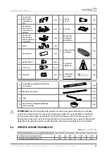
2.1 

COMPOSITION DE L’ENSEMBLE fOURNI

COMMANDE EN ASSORTIMENT

1

Commande

1 pcs.

11 Vis  4 × 18

2 pcs.

2

Console de porte

1 pcs.

12

Vis  3,9 × 9,5 

(taillant de 

mèche)

2 pcs.

Tableau 1

Содержание Levigato LG Series

Страница 1: ...operation manual Drives Levigato LG series for garage doors English Montage und Betriebsanleitung Antriebe Levigato Serie LG für Garagentore Deutsch Manuel d Installation et d Utilisation Commandes Levigato série LG de portes de garages Français ...

Страница 2: ......

Страница 3: ... 235 330 68 90 90 330 90 LGR 3300B LGR 3300C 2590 mm LGR 3600B LGR 3600C 2890 mm LGR 4200B LGR 4200C 3490 mm LGR 3300B LGR 3300C 3300 mm LGR 3600B LGR 3600C 3600 mm LGR 4200B LGR 4200C 4200 mm 120 68 LG R 3300B LG R 3300C 3630 mm LGR 3600B LGR 3600C 3930 mm LGR 4200B LGR 4200C 4530 mm 5 55 45 19 105 30 max110 19 33 64 150 73 130 70 135 max 1400 235 330 68 90 90 330 90 120 68 Dimension is provided ...

Страница 4: ...50 М 1 RX photocells receiver 4 0 5 mm2 4 1 mm2 2 TX photocells transmitter 2 0 5 mm2 2 1 mm2 3 Key switch 2 0 5 mm2 2 1 mm2 4 Lamp 2 0 5 mm2 2 1 mm2 5 Antenna RG58 max 20 m KETTE LÄNGE 1 M 20 M LÄNGE 20 M 50 M 1 Empfänger von RX Fotoelementen 4 0 5 mm2 4 1 mm2 2 Empfänger vonTX Fotoelementen 2 0 5 mm2 2 1 mm2 3 Schlüsseltaster 2 0 5 mm2 2 1 mm2 4 Lampe bzw Signalleuchte 2 0 5 mm2 2 1 mm2 5 Antenn...

Страница 5: ...LEVIGATO DRIVES LG SERIES LEVIGATO ANTRIEBE SERIE LG COMMANDES LEVIGATO SERIE LG 3 Fig Abb 3 Fig Abb 4 Fig Abb 5 Fig Abb 6 Fig Abb 7 Fig Abb 8 Ø10 5 Fig Abb 9 Fig Abb 10 ...

Страница 6: ...LEVIGATO DRIVES LG SERIES LEVIGATO ANTRIEBE SERIE LG COMMANDES LEVIGATO SERIE LG 4 Fig Abb 11 L Fig Abb 12 Fig Abb 13 Fig Abb 14 Fig Abb 15 ...

Страница 7: ...LEVIGATO DRIVES LG SERIES LEVIGATO ANTRIEBE SERIE LG COMMANDES LEVIGATO SERIE LG 5 Fig Abb 16 Fig Abb 17 Fig Abb 18 Fig Abb 19 Fig Abb 20 Fig Abb 21 Fig Abb 22 ...

Страница 8: ... STOP NC PHOTOCELLS NC PHOTOTEST LAMP 230 V max100 W 6 3 SBS SL LL 230V S GND 24V 24V GND 12V SE PH1 PH T Antenna 12 V DC max 120 mA 24 V DC max 120 mA STOP NC PHOTOCELLS NC 6 3 SBS SL LL 230V S GND 24V 24V GND 12V SE PH1 PH T A Fig Abb 24 12 240V AC DC SBS SL LL 230V S GND 24V 24V GND 12V SE PH1 PH T SBS SL LL 230V S GND 24V 24V GND 12V SE PH1 PH T ...

Страница 9: ...g Abb 25 12 24V AC DC SBS S GND 24V 24V GND 12V SE PH1 PH T SL LL 230V 12 24V COM AC DC SBS S GND 24V 24V GND 12V SE PH1 PH T SL LL 230V NO NC Fig Abb 26 SBS S GND 24V 24V GND 12V SE PH1 PH T SL LL 230V SBS S GND 24V 24V GND 12V SE PH1 PH T SL LL 230V 12 24V AC DC 12 24V COM AC DC NO NC ...

Страница 10: ...N GN WH SBS S GND 24V 24V GND 12V SE PH1 PH T SL LL 230V SBS S GND 24V 24V GND 12V SE PH1 PH T SL LL 230V GN green BN brown WH white GN grün BN braun WH weiß GN vert BN marron WH blanc Fig Abb 28 8K2 SBS S GND 24V 24V GND 12V SE PH1 PH T SL LL 230V SBS S GND 24V 24V GND 12V SE PH1 PH T SL LL 230V ...

Страница 11: ...TO DRIVES LG SERIES LEVIGATO ANTRIEBE SERIE LG COMMANDES LEVIGATO SERIE LG 9 Fig Abb 29 Fig Abb 30 SBS S GND 24V 24V GND 12V SE PH1 PH T SL LL 230V SBS S GND 24V 24V GND 12V SE PH1 PH T SL LL 230V Fig Abb 31 ...

Страница 12: ......

Страница 13: ...r assembly 17 4 Mounting 17 4 1 Drive rail and drive mounting 17 4 2 Manual release 18 5 Electrical interfaces 19 6 Adjustment 20 6 1 Adjustment of the door position 21 6 2 Radio control setup 23 6 3 Settings of operation values 27 6 4 Factory reset 30 7 Testing and commissioning 30 8 Technical maintenance 31 9 Troubleshooting 31 10 Storage transportation and disposal 33 11 Warranty obligations 33...

Страница 14: ... the mains circuit If the master switch or similar device is out of sight then attach a safety sign stating Do not turn on People are working and take measures preventing the possibility of accidental restoring the power supply The manufacturer and supplier do not directly control the doors installation maintenance and operation of the drive and automation devices and are not responsible for the s...

Страница 15: ...talled in an accessible place so that the power cord power cable of the drive is not located in the area of door movement and other moving parts The electrical network must be equipped with a protective earth Please make sure that the section of the mains supply to which the drive is connected is equipped with the short circuit protection device Residual Current Device RCD automatic switch or anot...

Страница 16: ...f safety devices photocells Stop etc on a monthly basis Please follow the safety measures when using the power cable fully insert the plug into the socket when taking the plug out of the socket do not pull by the cord do not use a socket with bad contacts do not touch a plug with wet hands do not damage the power cable do not twist the cable do not bend and do not stretch it do not place heavy obj...

Страница 17: ...rary loss of mains power the drive rail can be released which will allow the door leaf to be operated manually 2 1 DELIVERY SCOPE DRIVE SET 1 Drive 1 pc 11 4 18 Screw 2 pcs 2 Door bracket 1 pc 12 Screw 3 9 9 5 drill point 2 pcs 3 Bracket to mount the rail on the wall 1 pc 13 Dowel 8 19 5 1 pc 4 Bracket to mount the rail on the ceiling 2 pcs 14 Stopper 1 pc 5 Bracket to mount the drive on the rail ...

Страница 18: ...o 2 4 m cycles hour 18 Maximum time of continuous operation at the force 150 N corresponds to the maximum force of the balanced door leaf 20 minutes Time of illumination after the door stops moving This parameter is regulated in the range 0 500 s default value is 30 s Remote control 868 15 0 15 MHz dynamic code maximum 64 remote controls Protection class I Protection degree IP20 Working temperatur...

Страница 19: ...holes in the door leaf metal Y Y ATTENTION Limit the drilling depth during drilling Do not allow through drilling of the door leaf Install the rail fastening bracket on the wall on the drive rail using two M8 16 bolts and two M8 nuts fig 5A The product construction allows turning of the bracket by 90 in relation to the rail during installation fig 5B e g to mount the rail on the ceiling without su...

Страница 20: ...r break the drive In cases when the drive rail is fastened to the ceiling without suspension strips install the drive on the rail beforehand Ensure its integrity during further mounting operations Ensure the necessary length of the release cable The manual release cable should be located at a height not less than 1 8 m Put the release label on the cord fig 18 Make a tie on the end of the cable and...

Страница 21: ... figure 24 connection of a signal lamp with built in antenna figure 25 photocells connection figure 26 connection of photocells with PHOTOTEST function figure 27 connection of optical safety margin figure 28 connection of resistive safety margin CONTACT DESCRIPTION SL LL Alarm lamp or illumination lamp connection output see fig 24 By default the output is set to work in the SL lamp mode signal lam...

Страница 22: ...of the antenna screening conductor Connection input of the antenna signal conductor The connector fig 29 used to connect the 24V DC 1 2 Ah battery The battery gives the opportunity to open the door in the emergency mode in case of supply voltage disconnection The full charge time of the battery is 48 hours The operation of the devices is shown by LEDs fig 30 LED INDICATION DESIGNATION ILLUMINATES ...

Страница 23: ...PEN position the carriage rail should be at a distance 20 mm from the support installation of support is compulsory fig 16 5 Press the button after that a dot will appear on the display which means the OPEN position 6 Using the button or set the door in the CLOSED position ATTENTION Avoid excessive pressing of the door leaf against the doorway in the CLOSED position After programming the end posit...

Страница 24: ... moves to the CLOSED position Movement continues to the upper panel support and after that a dot appears on the display 4 The door automatically moves to the OPEN position 5 The door automatically moves to the CLOSED position 6 rc is shown on the display which means that the recording of remote controls in step by step mode is expected 7 Press the selected control button on the remote control thre...

Страница 25: ...he remote control F7 two settings of deleting the remote control F8 F9 and the setting of deleting all remote controls F0 MENU SETTING DESCRIPTION P2 F1 Recording of one button with SBS control mode F2 Recording of two buttons with SBS and PE control modes F3 Recording of two buttons with SBS and LL control modes F4 Recording of three buttons with SBS and LL control modes F5 Recording of four butt...

Страница 26: ...ed remote control when you need to record another button of the remote or record the remote in another mode it must first be deleted from memory The pressed button when recording will control the remote in the first mode in the list tab 10 All other buttons of the remote control will be recorded automatically in the order specified in the table 10 modes refers to the settings in which several butt...

Страница 27: ...able12 describes the settings it is used when there is a remote control but the information for the remote control number in the drive memory is not available 1 Press and hold the button for about 5 secs to enter the programming mode 2 After the appearance of P1 inscription press the button 3 After the appearance of P2 inscription press the button 4 With the button or select the required setting F...

Страница 28: ...s the button A dot will disappear from the display this means that the remote control with the selected number is deleted from the memory 5 In three seconds the next number of the remote control will appear on the display To exit the programming mode press the button or wait for 15 seconds until automatic exit the setup menu Deleting all remote controls 1 Press and hold the button for about 5 secs...

Страница 29: ... the required menu inscription press the button 4 With the button or select the required setting F 5 After the appearance of the required setting inscription press the button 6 The value of setting will be on a display The value will be with a dot With the button or select the required value of setting 7 After the appearance of the required value of setting press the button The value will be with ...

Страница 30: ...gn object by the drive will result in an immediate stop of movement ATTENTION Force and speed settings are made by the manu facturer The factory settings of force and speed ensure compli ance with the requirements of the safety standard EN 12453 type C of built in device for a certain type of ALUTECH doors with the permissible limit parameters sec tion 2 2 Technical parameters In other cases a spe...

Страница 31: ...ctronic sensor optosensor OSE no OFF 01 sensor 8 2 kOhm 02 optosensors no F5 Photocellsblockingclosetothefloorlevel andthesafetysensor input SE The setting specifies the distance from the floor where the photocells and the safety sensors are ignored no OFF 01 02 03 99 99 maximum 200 mm no P8 F1 ThesettingofoutputSL LLinsignallamp modeSL continuous or flashing no flashing on continuous on F2 Thedel...

Страница 32: ...lly open and close the door several times Make sure that there are no points of increased resistance to motion and there are no assembly and adjustment defects of the doors and drive Return to the blocked state perform the full open close cycle Make sure that the door moves in the required directions the leaf of the door moves smoothly At the end of opening and closing the door moves slowly check ...

Страница 33: ...e safety rules Perform scheduled maintenance at least once every six months Scheduled maintenance shall include read the section 1 General warnings and safety rules check the wear of the set elements paying attention to oxidization of the components Replace all parts and units with an unacceptable degree of wear Use original parts from the manufacturer check the correctness of the door stop in its...

Страница 34: ... movement when closing the indicator shows error number E1 Optical sensors of safety margin are activated Check the performance of the safety margin replace the failing components if necessary check the selected safety margin mode in the menu The drive does not start working when command is given the indicator shows error number E4 Error occurred during phototest Check the performance of photocell...

Страница 35: ...During the warranty period the defects caused by the Manufacturer are repaired by the service department providing warranty maintenance Note the parts replaced by the service department performing the product repair become the department s property Warranty is not applied in the following cases violation of storage transportation operation and mounting rules mounting adjustment repair remounting o...

Страница 36: ...mation about repairing organisation List of repairs Repair date day month year LS Signature of the person in charge of repair____________ __________________________ signature full name Information about repairing organisation List of repairs Repair date day month year LS Signature of the person in charge of repair____________ __________________________ signature full name 14 STATEMENT OF COMPLIANC...

Страница 37: ... 42 4 Montage 42 4 1 Antriebsschienen und Antriebsmontage 42 4 2 Manuelle Entriegelung 43 5 Elektroanschlüsse 44 6 Einstellung 46 6 1 Einstellung der Torposition 46 6 2 Einstellung der Fernbedienung 49 6 3 Einstellung der Betriebswerte 52 6 4 Reset auf Werkeinstellungen 55 7 Funktionstest und Inbetriebnahme 56 8 Technische Wartung 57 9 Störungen und Störungsbehebung 57 10 Lagerung Transport und En...

Страница 38: ... Hersteller haftet nicht für die Schäden die auf die Änderungen am Produkt oder dessen unsachgemäße Verwendung zurückzuführen sind Bei Montage Reparatur Wartungs Reinigungs oder sonstigen Arbeiten sowie Anschlüssen innerhalb des Antriebs ist die Anlage stromlos zu schalten Wenn sich die Schalteinrichtung außer Sichtweite befindet ist der Schild Nicht einschalten Es wird gearbeitet anzubringen und ...

Страница 39: ...egelungsschloss Außenschloss für die Entriegelung der Antriebsschiene wird separat geschlossen vorgesehen werden Verwenden Sie die manuelle externe Entriegelung nur bei geschlossenem Tor Die Oberflächen der Installationsorte des Antriebssystems und seiner Komponenten sollen fest sein und als zuverlässige und steife Unterstützung dienen Ergreifen Sie andernfalls Maßnahmen zur Verstärkung der Instal...

Страница 40: ...n dasTor vollständig angehalten und unbe weglich ist Personen und Fahrzeuge dürfen das Tor nicht passieren wenn sich das Tor bewegt Niemand kann unter dem offenen Tor sein Die Tore mit Automatikantrieb können in einem unerwarteten Moment auslösen Seien Sie vorsichtig bei der manuellen Entriegelung des Tors Abschnitt 4 2 Manuelle Ent riegelung da geöffnete Tore durch Lockern oder Brechen der Federn...

Страница 41: ...en diese Anforderung kann zur Beschä digung des Produkts zu Fehlfunktionen und zu Feuer oder anderen gefährlichen Situationen führen Das Antriebssystem und das Tor sollen regelmäßig gewartet werden um einen effizienten und sicheren Betrieb zu gewährleisten Technische Wartung und Reparatur sollen von den ausfüh renden Personen dokumentiert werden und der Eigentümer soll diese Unterlagen aufbewahren...

Страница 42: ...versehrtheit zu prüfen Bei Reklamationen ist der Hersteller unverzüglich zu informieren Befestigungsteile Dübeln Anker die für die Befestigung der Bauteile an der Wand und Decke erforderlich sind sind nicht im Lieferumfang enthalten da deren Auswahl vom Baustoff und Stärke der Wand in der sie befestigt werden abhängig ist 2 2 TECHNISCHE DATEN KENNDATEN LG 600F 868 LG 600F 868 GB LG 800 868 LG 800 ...

Страница 43: ...dellen LG 600F 868 GB LG 800 868 GB LG 1000F 868 GB LG 1200 868 GB wird der Netzstecker Typ G verwendet Typ der Stromleitungen vom Antrieb H05VV F 3G0 75 mm2 ARTIKEL TYP DER ANTRIEBSSCHIENE MAXIMALE HÖHE DES TORES MM LGR 3300B Zahnriemensystem 2400 LGR 3600B Zahnriemensystem 2700 LGR 4200B Zahnriemensystem 3300 LGR 3300C Kettensystem 2400 LGR 3600C Kettensystem 2700 LGR 4200C Kettensystem 3300 Abm...

Страница 44: ... an der Antriebsschiene mithilfe von zwei Bolzen M8 16 und zwei Muttern M8 Abb 5A befestigen Die Konstruktion ermöglicht es das Sturzgelenk bei der Montage um 90 zur Antriebsschiene zu drehen Abb 5В z B bei der Montage der Antriebsschiene an der Decke ohne Abhängung die Montagestelle des Sturzgelenkes festlegen Abb 6 Der Freiraum zwischen der Antriebsschiene und der maximalen oberen Endlage des To...

Страница 45: ...ann zu Beschädigungen führen Sollte die Antriebsschiene ohne Abhängewinkel montiert werden wird der Antrieb an der Schiene vor der Befestigung montiert Folgendes ist zu beachten notwendige Länge des Entriegelungsseiles festlegen Das Seil zur manuellen Entriegelung soll in der Höhe von 1 8 m befestigt werden Setzen Sie das Schild über Entriegelung auf das Seil Abb 18 Am Ende des Seiles einen Knoten...

Страница 46: ...chlusszeichnung und Bezeichnungen sind auf der Abb 23 angeführt Auf den Abb 24 28 sind Anschlussbeispiele für ALUTECH Komponenten Accessoires angegeben Abb 24 Anschluss der Signalleuchte mit integrierter Antenne Abb 25 Anschluss der Lichtschranke Abb 26 Anschluss der Lichtschranke mit der Funktion Fototest Abb 27 Anschluss der optischen Sicherheitsleiste Abb 28 Anschluss der widerstandsfähigen Sic...

Страница 47: ...chal ten und danach folgendes Einschalten der Stromzuführung des Sendegerätes der Lichtschran ke eine automatische Prüfung der Funktion der Lichtschranke geleistet Schema für den Anschluss der Lichtschranke Abb 26 In den Einstellungen Kapitel 6 Einstellung P7 F3 erfolgt das Einschalten des entsprechenden Menüpunktes Nachdem dasTor im Standby Modus vollständig geschlossen ist ist der PH Т Ausgang d...

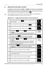
Страница 48: ... sind führt der Antrieb die Steuerbefehle nicht aus auf dem Bildschirm werden zwei Punkte angezeigt Y Y Nach dem Einstellen der Endpositionen werden die Werte der Menüeinstellungen P5 und P6 automatisch auf die werkseitigen Einstellungen zurückgesetzt Tabelle 16 EINSTELLUNG P1 F1 manuelle Programmierung der Endlagen 1 Halten Sie dieTaste 5 Sekunden lang gedrückt bis das Einstellungsmenü aufgerufen...

Страница 49: ... Tor Auf und Tor Zu auf Befehl wird automatisch mit automati schem Übergang zum Speichern der Handsender im Einstellungsmenü P2 F1 Tab 9 ausgeführt Y Y ACHTUNG Prüfen Sie bitte dass der Anschlag für die Position Tor Auf an der Antriebsschiene installiert ist Abb 16 1 Halten Sie dieTaste und gleichzeitig 5 Sekunden lang gedrückt ACHTUNG Gleich danach beginnt automatischerTorlauf Kontrollieren Sie d...

Страница 50: ...Zwischenposition Personendurchgang Der Steuerbefehl in die Position Personendurchgang wird nur vom Handsender ausgeführt der mit diesem Steuermodus Menü P2 Modus PE gespeichert wurde Der Steuerbefehl in die Posi tion Personendurchgang wird aus jederTorstellung End oder Zwischenstellung ausgeführt Die Einstellung der Position Personendurchgang wird nur ausgeführt wenn die Endlagen eingestellt sind ...

Страница 51: ...vorhanden ist jedoch die Information vorliegt unter welcher Nummer der Handsender gespeichert ist F0 Löschen aller gespeicherten Handsender SBS Steuermodus step by step Befehlsfolge Auf Stopp Zu Stopp Auf OP Steuermodus Auf Öffnungsbefehl CL Steuermodus Zu Schließbefehl STOP Steuermodus STOPP Der Befehl dasTor aufzuhalten PE Steuermodus Personendurchgang Befehl zum teilweisen Öffnen desTores sowei...

Страница 52: ... dieTaste 6 Auf dem Bildschirm erscheint die Anzeige rc dass heißt das Speichern des Handsenders steht an 7 Die gewünschte Steuertaste die erste Steuertaste auf dem Handsender dreimal betätigen 8 Auf dem Bildschirm erscheint automatisch die Nummer die für das Einlernen im Antrieb angeboten wird mit derTaste oder kann die Nummer geändert werden 9 Drücken Sie zur Bestätigung dieTaste danach wird auf...

Страница 53: ...sender nicht abgespeichert werden wird auf dem Bildschirm no angezeigt 9 Für die Einstellung F8 drücken Sie dieTaste Auf dem Bildschirm erlischt der Punkt Das heißt dass der Handsender gelöscht wurde 10 In 3 Sekunden schaltet das System automatisch auf das Erwarten des Signals vom nächsten Handsender um Um das Einstellungsmenü zu verlassen drücken Sie dreimal dieTaste oder warten Sie 15 Sekunden l...

Страница 54: ...ücken und halten Sie dieTaste 5 Sekunden lang gedrückt bis auf dem Bildschirm der Punkt erschein Das bedeutet dass alle Handsender gelöscht werden 7 Um das Einstellungsmenü zu verlassen drücken Sie dieTaste zweimal oder warten Sie 15 Sekunden bis zum automatischenVerlassen des Einstellungsmenüs Y Y ACHTUNG Bevor Sie die Handsender zum ersten Mal programmieren löschen Sie alle zuvor gespeicherten H...

Страница 55: ...INSTELLUNG P1 F4 Kontrolle bzw Nachstellen der Endpositionen in 100 Zyklen des Öffnens Schließens desTores nach dem Anschlag in der Position Tor Auf Abb 16 no Abgeschaltet on Eingeschaltet no P3 F1 Automatischer Betriebsmodus DasTor wird durch ein kurzes Drücken auf der Steuereinheit gesteuert on F2 Manueller Betriebsmodus DieTorbewegung wird ausgeführt wenn das Steuergerät bzw dieTaste und und SB...

Страница 56: ... 12453 Gerätetyp E F2 Antriebskraft beim Schließen Wenn ein Hindernis vom Antrieb beim Schließen erkannt wird stoppt die Steuerung die Fahrt sofort und danach kommt es zum vollständigen Öffnen P6 F1 Geschwindigkeit derTorfahrt beim Öffnen In der werkseitigen Einstellung ist der Antrieb auf die Höchstgeschwindigkeit eingestellt F2 Geschwindigkeit derTorfahrt beim Schließen In der werkseitigen Einst...

Страница 57: ...vom Fußboden angegeben wo Signale der Lichtschranke und der Sicherheitsleiste ignoriert werden no Abgeschaltet 01 02 03 99 99 Maximum 200 mm no P8 F1 Betrieb des Ausgangs SL LL imWarnleuchte Modus SL ununterbrochen oder blinkend no blinkend on ununter brochen on F2 Verzögerte Startzeit Vorschaltung der Warnleuchte Binnen dieses Zeitraumes funktioniert dieWarnleuchte SL und signalisiert über den be...

Страница 58: ...die Montage und die Einstellungen des Tors und des Antriebs nicht fehlerhaft sind Das Tor in den verriegelten Zustand zurück bringen den vollen Zyklus Auf Zu durchführen Prüfen dass das Tor in die bestimmten Richtungen verfährt und das Torblatt sich gleichmäßig bewegt Am Ende der Auf und Zufahrt bewegt sich das Tor langsam die Spannung des Gurtes des Kettes in der Antriebsschiene prüfen und gegebe...

Страница 59: ...ne effektive und sichere Arbeit ist das Antriebssystem einer planmäßigen Wartung zu unterziehen Wartungsarbeiten sind streng nach den geltenden Normativdokumenten Hin weisen dieser Anleitung und den Anleitungen anderer miteinbezogenen Einrichtungen unter Beachtung der Sicherheitsvorschriften durchzuführen Die planmäßige Wartung lediglich jede 6 Monate durchführen Folgendes ist bei Wartungsarbeiten...

Страница 60: ...iebsschiene eingebaut ist BeimTorbetrieb reagiert der Antrieb nicht auf Hindernisse auf der optischen Achse der Lichtschranke Fotoelemente sind nicht intakt oder der Betriebsmodus der Lichtschranke ist nicht korrekt Leistungsfähigkeit der Lichtschranke prüfen gegebenenfalls auswechseln den Modus für die Lichtschranke im Menü prüfen Der Antrieb hält während Auffahrt an oder reversiert während Zufah...

Страница 61: ...ehlernummer EE wird angezeigt Antriebsstörung falsches Signal des Getriebemotor Encoders Wenden Sie sich an den Kundendienst Nachdem der Steuerbefehl ausgegeben wurde blinkt die im Antrieb eingebaute Hintergrundbeleuchtung Ein Fehler tritt beim Betrieb des Antriebes auf Wenn die Hintergrundbeleuchtung blinkt überprüfen Sie die Fehleranzeige auf dem Antriebssdisplay Reparieren Sie das Antrieb gemäß...

Страница 62: ...chäden die durch Auftraggeber oder Dritte verursacht sind bei Fehlern und Störungen die durch ausfallende optische Prüfung undWartung bedingt sind beim Fehlen der ausgefüllten Anleitung Bei Service Fragen wenden Sie sich bitte an die Organisation die die Installation von Automatik durchgeführt hat 12 INBETRIEBNAHMEBESCHEINIGUNG Fabrikationsnummer und Herstellungsdatum Daten vom Etikett Daten über ...

Страница 63: ...rdatum Tag Monat Jahr Stempel Unterschrift des Verantwortlichen für die Reparatur _______________________________________ Unterschrift Name des Unterzeichners 14 ZERTIFIKATE Kopien der Konformitätserklärungen sind unter http www alutech group com de products other automatics documents erhältlich Hergestellt in China Hersteller Shanghai Baolu Technology Co Ltd 8 f Xianglu Industry Park 3009 Gudai R...

Страница 64: ... 1 Installation de la cremaillere principale de commande et de la commande elle même 69 4 2 Déblocage manuel 70 5 Connexions électriques 71 6 Réglage 72 6 1 Réglage de position de la porte 73 6 2 Réglage de la télécommande 75 6 3 Réglage des paramètres de fonctionnement 79 6 4 Réinitialisation de tous les réglages par défaut 82 7 Vérification et mise en service 82 8 Entretien 83 9 Anomalies de fon...

Страница 65: ...it et leur utilisation inapro priée sont interdites Le fabricant décline toute responsabilité pour tout dommage causé par une modification non autorisée ou une utilisation inappropriée du produit Pendant des travaux le montage la réparation l entretien le nettoyage etc et des branche ments à l intérieur de la commande faites très attention que le curcuit d alimentation éléctrique ne soit pas conne...

Страница 66: ...urez le débloquage de la commande quand les portes sont fermées En cas de l absence de portillon sur le vantail de porte ou de l absence d une entrée supplémen taire dans le local il est nécessaire de prévoir une unité de déverrouillage manuel d urgence un verrou externe pour débloquer la crémaillère principale de commande il est fourni séparément N utilisez le déblocage manuel externe que quand l...

Страница 67: ... porte assurez vous qu il n y ait ni gens ni animaux ni moyens de transport ou ni objets dans la zone de risque Suivez le mouvement de la porte jusqu à la fermeture ou ouverture complète Le passage par la porte est autorisé quand la porte est complètement arrêtée et immobile Il est interdit de passer par la porte lorsque la porte est en mouvement Il est interdit de se trouver sous la porte ouverte...

Страница 68: ...ses composants doivent être suffisament éloignés de toute source de chaleur et de flammes nues Le non respect de cette exigence peut entraîner un sérieux dommage du produit provoquer un fonctionnement anormal et même déclencher un incendie ou d autres incidents Le système de commande et la porte doivent être soumis à un entretien régulier pour garantir un fonctionnement efficace et sécurisé L entr...

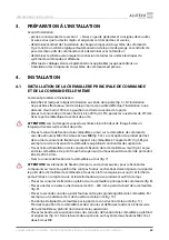
Страница 69: ...mmande au complet 1 pcs 20 Bande de suspension 2 pcs 21 Tige 1 pcs 22 Partie de l assemblage de déblocage bille manivelle 2 pcs Y Y ATTENTION Lors de la réception du produit assurez vous que le jeu fourni est complet et que les composants n ont subi aucun dommage visible En cas de problème contactez le fournisseur du produit Les éléments de fixation tampons ancres nécessaires pour la fixation des ...

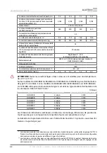
Страница 70: ...sont valables pour une température de 20 C 5 C Sur les modèles LG 600F 868 LG 800 868 LG 1000F 868 LG 1200 868 la prise d alimentation de type E F est utilisée Sur les modèles LG 600F 868 GB LG 800 868 GB LG 1000F 868 GB LG 1200 868 GB la prise d alimentation de type G est utilisée Type de câble d alimentation de la commande H05VV F 3G0 75 mm2 ARTICLE TYPE DE CRÉMAILLÈRE HAUTEUR MAXIMALE DE LA POR...

Страница 71: ...ation de la crémaillère au mur sur la crémaillère de commande avec deux boulons M8 16 et deux écrous M8 fig 5A La conception du produit permet de tourner la console de fixation par rapport à la crémaillère à l angle de 90 fig 5B par exemple lors de la fixation de la crémaillère au plafond sans bandes de suspension Tracez le lieu d installation de la console de fixation de la crémaillère au mur fig...

Страница 72: ... commande à la crémaillère à l avance Assurez vous de son intégrité lors des opérations d installation ultérieures Préparez le cordon de déblocage en fonction de la longueur désirée Le cordon de déblocage manuel doit être placé à une hauteur d au moins 1 8 m Posez sur le cordon le signe de déblocage fig 18 A l extrémité du cordon il faut faire un noeud et le coincer entre les deux moitiés des bill...

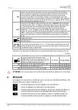
Страница 73: ...CH fig 24 connexion de la lampe témoin avec antenne integrée fig 25 connexion des photocellules fig 26 connexion des photocellules avec la fonction Phototest fig 27 connexion du bord de sécurité optique fig 28 connexion du bord de sécurité résistif CONTACTS DESCRIPTION SL LL Porte avec connexion d une lampe témoin ou une lampe d éclairage fig 24 Par défaut le contact est réglé pour fonctionner en ...

Страница 74: ...e PH Т est activée Blindage de l antenne Signal de l antenne Connecteur fig 29 pour batterie 24 DC 1 2 A h La batterie permet d effectuer l ouverture de la porte en mode de secours quand la tension de réseau est désactivée Il faut 48 heures pour que la batterie atteigne sa pleine charge L indication des dispositifs est effectuée au moyen de diodes électroluminescentes fig 30 PHOTOCELLULE DESTINATI...

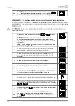
Страница 75: ... mettez la porte en position Ouverte ATTENTION Danslaposition Ouverte lechariotdelacrémaillèredoitêtreà unedistancede 20mmdelabutée L installationdelabutéeestobligatoire fig 16 5 Appuyez sur le bouton après l avoir appuyé un point apparaît à l afficheur ce qui signifie la mémorisation de la position Ouverte 6 Avec les boutons ou si nécessaire mettez la porte en position Fermée ATTENTION Evitez d e...

Страница 76: ...eut être exécuté de manière similaire pour le choix du menu P1 et réglage F3 2 La porte se déplace automatiquement au point de contact du chariot de crémaillère avec la butée ensuite un point apparaît à l afficheur 3 La porte se déplace automatiquement en position Fermée jusqu à ce que sa face supérieure ne touche pas la butée ensuite un point apparaît à l afficheur 4 La porte se déplace automatiq...

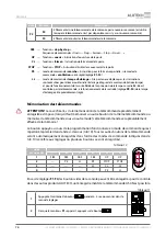
Страница 77: ...n marche 7 Pour quitter le menu de réglages appuyez 2 fois sur le bouton ou attendez 15 sec jusqu à la sortie automatique du menu de réglages 6 2 RÉGLAGE DE LA TÉLÉCOMMANDE Dans le menu P2 tab 9 six réglages de mémorisation des télécommandes sont présents F1 F6 la détermination du numéro de commande dans la mémoire F7 deux réglages de l effacement de la télécommande de la mémoire F8 F9 et le régla...

Страница 78: ...mande si le fonctionnement de la sortie LL réglage P8 F4 de la lampe d éclairage a été préalablement réglé Mémorisation des télécommandes Y Y ATTENTION Le cas échéant si la rémémorisation de la télécommande précédemment enregistrée s impose lorsqu il faut mémoriser un autre bouton de la même télécommande ou mémoriser la télécommande sous un autre mode cette télécommande sera préalablement effacée ...

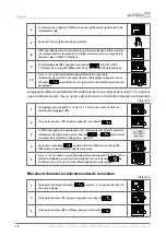
Страница 79: ...à l afficheur 10 La transition automatique à la mémorisation de la télécommande suivante se fait au bout de 3 sec Pour quitter le menu de réglages appuyez 3 fois sur le bouton ou attendez 15 sec jusqu à la sortie automatique du menu de réglages Effacement des télécommandes de la mémoire et détermination de numéro de commande dans la mémoire Le tab 12 contient les descriptions des réglages qui sont...

Страница 80: ...it dans le tab 13 lorsqu il n y a pas de télécommande mais le numéro de mémorisation de la télécommande est disponible 1 Analogiquement aux points 1 4 du tab 12 entrez dans le menu P2 et sélectionnez le réglage F9 2 Dès que la mention F9 apparaît appuyez sur le bouton 3 À l afficheur apparaît automatiquement la mention de numéro de la première télécommande mémorisée Aves les boutons ou sélectionne...

Страница 81: ...upprimez tous les numéros des télécommandes et mémorisez les de nouveau 6 3 RÉGLAGE DES PARAMÈTRES DE FONCTIONNEMENT Le tab 15 présente l exemple d une entrée dans le menu de réglages et définition des paramètres valeur du fonctionnement 1 Appuyez et maintenez le bouton pendant 5 sec pour entrer dans le menu de réglages 2 Dès que la mention P1 apparaît avec le bouton ou le bouton sélectionnez le m...

Страница 82: ...depauseavantlafermeture automatique depuis la position piéton après le déclenchement des photocellules entrée de connexion PH1 Exécutable si la position de la porte piéton a été réglée réglage P1 F2 no Y YSi la fermeture automatique est activée le temps de pause est réglé la fonction PHOTOTEST sera activée automatiquement le réglage P7 F3 on et l entrée de connexion PH1 ne sera activée que lors de...

Страница 83: ...te Les réglages installés doivent assurer un fonctionnement sécurisé et correct des portes conformément aux règlements en vigueur EN 12453 afin d éviter les dommages et les dégâts ainsi que les fausses alarmes L entrée dans le menu P5 et P6 par l utilisateur est bloquée P7 F1 Sélectiondumodedefonctionnementdes photocellules entrée PH1 L entrée est activé lors de l ouverture ou activé lors de la fe...

Страница 84: ...ment de la porte et le blocage de mouvement réglage te temps P8 F2 Lampe d éclairage LL fonctionne lors du mouvement de la porte et après l arrêt du mouvement réglage de temps P8 F3 no lampe témoin on lampe d éclairage no 6 4 RÉINITIALISATION DE TOUS LES RÉGLAGES PAR DÉFAUT La réinitialisation aux réglages d usine restitue les valeurs des paramètres définis par défaut lors de la livraison de la co...

Страница 85: ...au milieu entre les deux photocellules Assurez vous que dans tous les cas la commande réponde correctement au déclenchement des photocellules lors de la fermeture la porte s arrête et puis s ouvre complètement vérifier que la commande soit capable de détecter une interaction avec des objets étrangers à la fermeture Positionnez au sol un obstacle de 50 mm de hauteur En cas de contact de la porte av...

Страница 86: ...n ou le fusible est défectueux Vérifiez la tension d alimentation Vérifiez et remplacez si nécessaire le fusible les paramètres du fusible doivent correspondre aux instructions L ordre envoyé par la télécommande n est pas exécuté Le code de commande n est pas mémorisé par la télécommande Rentrez le code correspondant à l ordre désiésur le boitier de la télécommande L ordre n est pas effectué par l...

Страница 87: ...ou de l utilisation trop intensive Ne sollicitez pas la porte pendant une quinzaine de minutes le temps que les éléments se refroidissent Attention de ne pas faire fonctionner la porte à une intensité supérieure à celle recommandée Au cours des derniers réglages avant la mise en route un code d erreur E8 va s afficher Soit la butée n est pas correctement installée sur la crémaillère soit en positi...

Страница 88: ...ation ou modification du produit par des personnes non autorisées dommages causés par une installation électrique non conforme aux recommandations du fabricant dégats des eaux entraînant la corrosion du produit cas de force majeure incendies foudres inondations tremblements de terre et autres catastrophes naturelles erreurs de montage et d assemblage du produit par le client ou par des tiers dysfo...

Страница 89: ...nseignements sur la société agrée pour les réparations Liste des réparations Date des réparations Date mois année SL Signature de la personne Responsable de l installation______________________________ Signature Nom complet 14 RENSEIGNEMENTS SUR LA CERTIFICATION Les copies des déclarations de conformité sont disponibles à l adresse suivante http www alutech group com fr products other automatics d...

Страница 90: ...LEVIGATO DRIVES LG SERIES LEVIGATO ANTRIEBE SERIE LG COMMANDES LEVIGATO SERIE LG 88 Angaben über Reparaturen während der Garantiefrist ...

Страница 91: ......

Страница 92: ...03 2019 10 Selitskogo str 220075 Minsk Republic of Belarus Tel 375 17 330 11 00 Fax 375 17 330 11 01 www alutech group com ...

Отзывы: