background image

 2. Mount

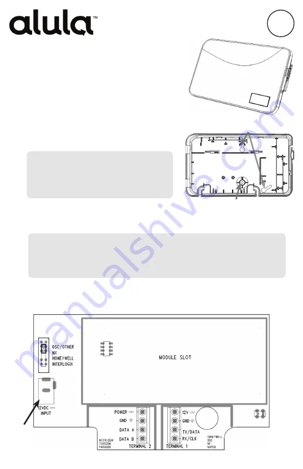
 the IGM to a wall using the mounting 

holes on the back plate.  

•  Do not mount inside of a metal can. The 

cellular antennas need to be in free air to 

communicate.

•  Mount as high in the building as possible 

to optimize cellular strength.

Verify proper enrollment and operation using your control panel’s installation manual.

IN

STALL

G

U I D E

I

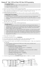
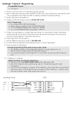
3. Program the panel to use the IGM. (Refer to the programming section for your panel.) 
4. Wire


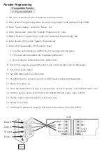
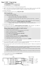
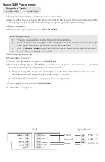
the panel to the IGM. (Refer to the programming section for a wiring diagram for 

your panel.)

•  The IGM power supply must have a battery backup. 
•  Maximum cable length to the panel:

18 gauge wire = 350 feet

22 gauge wire = 130 feet

24 gauge wire = 75 feet

Flex LTE IGM 

is an LTE cellular device that provides 

interactive services and home automation to existing 

security systems. 

Features

•  Connects panels to the LTE cellular network

•  Provides interactive services without panel replacement

•  5 year warranty

Installation

1. Set up an account

 with your interactive services provider.

Mounting Screw Locations

Wall Tamper (Do not over tighten mounting screw)

Not Used

Note: Be sure to verify that all codes are being properly reported to the central 

station after you have installed the IGM or modified any reporting program 

setting in the installer programming menu.


Resolution Compatibles

RE929X Interactive Gateway Mod

ule


LTE, Flex

Содержание RE929X Series

Страница 1: ...kup Maximum cable length to the panel 18 gauge wire 350 feet 22 gauge wire 130 feet 24 gauge wire 75 feet Flex LTE IGM is an LTE cellular device that provides interactive services and home automation to existing security systems Features Connects panels to the LTE cellular network Provides interactive services without panel replacement 5 year warranty Installation 1 Set up an account with your int...

Страница 2: ...er code in the IGM is not synchronized with the master code in the Vista panel If it is required to have the keypad lockout feature enabled it is critical that the system master code be set up as a contact for this account before connecting the module to the panel see step 2 above Also all changes to the system master code must be done at the user portal or dealer portal not at the keypad Failing ...

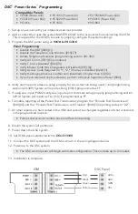
Страница 3: ...a Module Supervision Reset 902 4 Verify alarm report codes are setup properly for zones that are being used 1 64 programming section 320 349 System will report as Burg 130 if programmed as FF 5 If using Aux input PGM2 verify Aux input report codes are setup properly programming section 329 4 System will report as Fire 110 if programmed as FF 6 To enable reporting of the Period Test Transmission pr...

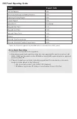
Страница 4: ... Table of all events reported by the IGM when connected to a DSC panel Zone Alarm Reporting Automatic Contact ID is not supported Manually programmed reporting codes are only supported for alarms on zones 1 64 320 324 and for alarms on the PGM2 Aux input 329 option 4 which is reported as zone number 99 If Report Codes have not been manually programmed for zone alarms zone alarm reporting codes def...

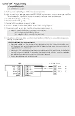
Страница 5: ...ettings automatically Enable opening and closing reports Set telephone line cut delay to 0 No TLM 8 Installation is complete Wait until the CS and platform LEDS have stopped blinking before entering program mode Additional Notes for NX Installations Some NX panels limit the number of non keypad devices that are supported Be sure that the panel you are connecting the IGM to does not have more than ...

Страница 6: ...tomation bus device 6 Power down the Concord system 7 Set the IGM s panel selector switch to INTERLOGIX 8 Connect the Concord panel and the IGM as shown in the wiring diagram 9 Power up the Concord system Concord programming if first time powered with a IGM Do not press any keys on the keypad for the first 2 minutes after power up After 2 minutes initiate a bus scan 8 installer code 1 Do not press...

Страница 7: ...l This code will be entered into the dealer portal later Do not use the same code as the master code 8 Exit to main page by pressing the home icon in the top left corner of the screen 9 Power the system down 10 Set IGM slider switch to DSC Other 11 Plug IGM into the serial connector via IGM Paradox cable sold separately 12 Power the system up 13 From the Dealer Portal of your service provider sele...

Страница 8: ...ent Keypad Address Power down the Napco system Find the mode jumper located on the Napco panel board Move the mode jumper to the CONFIG state Power up the Napco system The display should show 01 OUT OF SYSTEM Press 1 1 1 2 3 FUNCTION Cycle through the menu until you see Keypad Address Change the keypad address to an open keypad location Press enter or on off to save the entry Power down system and...

Страница 9: ...The IGM will automatically program it make sure all partitions are disarmed and dealer programming has been exited Programming starts as soon as a connection is made to the interactive server Once the connection is made programming willl last roughly 1 minute IGM will read Access Code 1 Reporting Code Configuration 9 The keypad s should display SYSTEM READY 10 Installation is complete Napco Panel ...

Страница 10: ...Texecom Programming Not yet supported coming soon ...

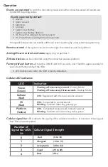
Страница 11: ...actory default button will reset the IGM if held for 5 seconds and if held for approximately 10 seconds will factory default the IGM LED flashes twice when the IGM is factory defaulted Cellular LED indicators LED Indication Power Green Flashing off once every second Primary Mode Flashing off once every three seconds Backup Mode Cellular Red ON Registered with the local cellular network CS Red ON C...

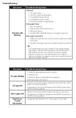
Страница 12: ...M to does not have more than the number of support devices connected i e some NX 4 panels only support 1 module in addition to keypads so they cannot support both an IGM and a wireless receiver Symptom Troubleshooting Steps CS Light Blinking 1 Verify the panel selection switch location 2 Verify wiring 3 Verify the panel is supported by the gateway both panel type and version CS Light Off Ensure an...

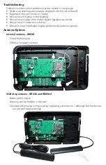
Страница 13: ... unit away from metal objects appliances ducts Move the unit closer to a window Move to one of the below higher performance antenna options Antenna Options Internal antenna RE038 Good Performance Offers a compact solution Wall drop antenna RE036 and RE036 0 Better performance Antenna can be hidden in the wall Cellular performance is improved by replacing just antenna 1 although both antennas can b...

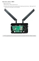
Страница 14: ...mance Offers optimal cellular performance Cellular performance can be improved by replacing just antenna 1 although both antennas can be side mount antennas Pull up gently on the antenna s connector to release it from the cellular module ...

Страница 15: ...This Page Intentionally Left Blank ...

Страница 16: ...GIES ELECTRONIC CON TROLS INC HONEYWELL INTERNATIONAL INC TYCO SAFETY PRODUCTS CANADA LTD NORTEK SECURITY CONTROL LLC TYCO SAFETY PRODUCTS CANADA LTD NAPCO SECURITY TECH NOLOGIES INC AND RESPECTIVELY ALULA PRODUCTS WILL FUNCTION WITH ONE OF EITHER INTERLOGIX FORMERLY GE HONEYWELL DSC 2GIG QOLSYS OR NAPCO SYSTEMS HOWEVER NO ALULA PRODUCT IS PRO DUCED BY ENDORSED BY NOR IS OFFICIALLY ASSOCIATED WITH...

Отзывы: