background image

KL3116 User Manual

24

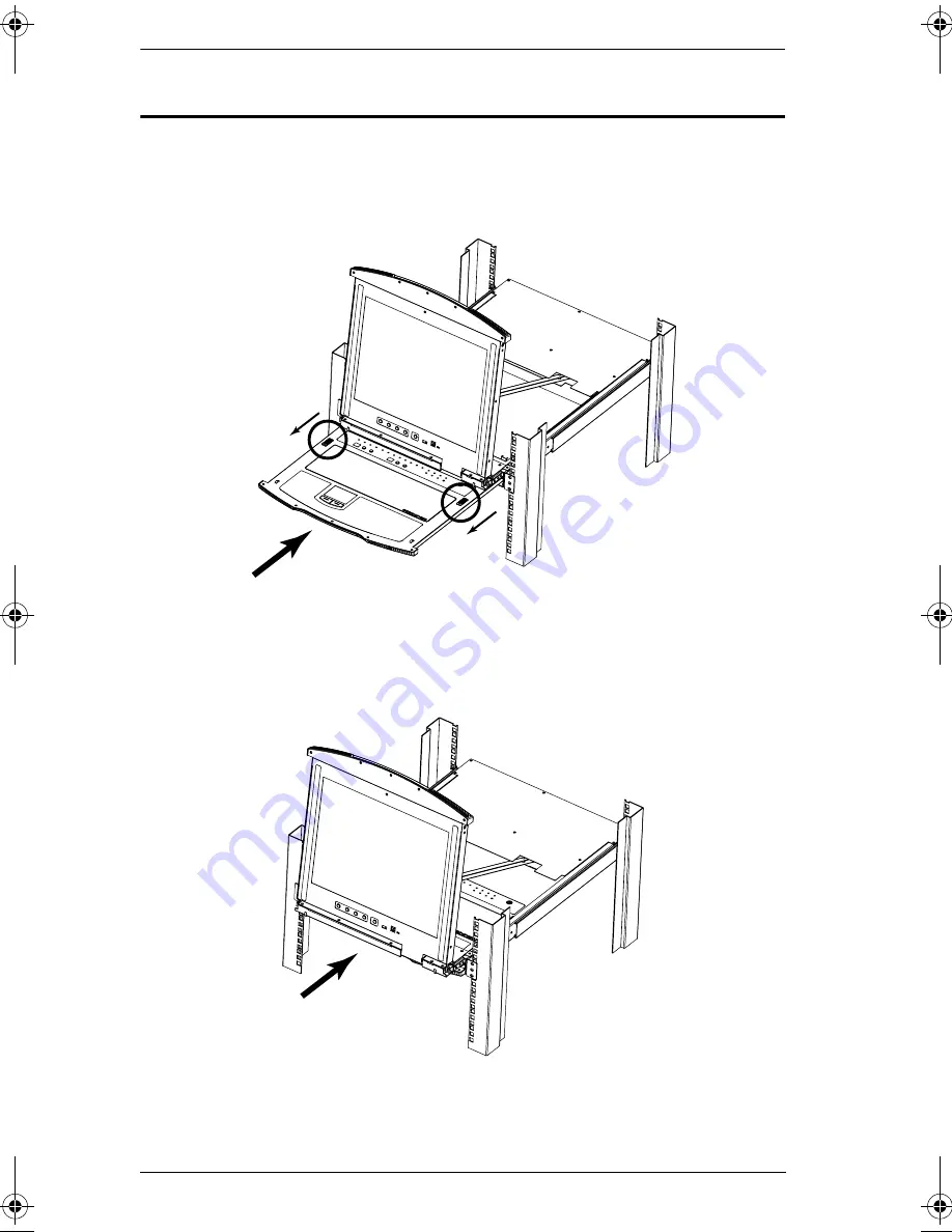
Closing the Console

1. Pull the release catches located on either side of the keyboard toward you 

to release the keyboard module, then slide the module slightly in.

2. Let go of the catches. Using the front handle, push the keyboard module 

all the way in.

kl3116.book  Page 24  Friday, July 7, 2006  11:54 AM

Содержание Hideaway KL3116

Страница 1: ...Hideaway LCD KVMP Switch KL3116 User Manual www altusen com ...

Страница 2: ...its are designed to provide reasonable protection against harmful interference when the equipment is operated in a commercial environment This equipment generates uses and can radiate radio frequency energy and if not installed and used in accordance with the instruction manual may cause harmful interference to radio communications Operation of this equipment in a residential area is likely to cau...

Страница 3: ... programs prove defective following their purchase the buyer and not the manufacturer its distributor or its dealer assumes the entire cost of all necessary servicing repair and any incidental or consequential damages resulting from any defect in the software The manufacturer of this system is not responsible for any radio and or TV interference caused by unauthorized modifications to this device ...

Страница 4: ...uid or aerosol cleaners Use a damp cloth for cleaning The device should be operated from the type of power source indicated on the marking label If you are not sure of the type of power available consult your dealer or local power company The device is equipped with a 3 wire grounding type plug This is a safety feature If you are unable to insert the plug into the outlet contact your electrician t...

Страница 5: ...isk of fire or electrical shock Do not attempt to service the device yourself Refer all servicing to qualified service personnel If the following conditions occur unplug the device from the wall outlet and bring it to qualified service personnel for repair The power cord or plug has become damaged or frayed Liquid has been spilled into the device The device has been exposed to rain or water The de...

Страница 6: ...ack is level and stable before extending a device from the rack Use caution when pressing the device rail release latches and sliding a device into or out of a rack the slide rails can pinch your fingers After a device is inserted into the rack carefully extend the rail into a locking position and then slide the device into the rack Do not overload the AC supply branch circuit that provides power ...

Страница 7: ... Check to make sure that all of the components are present and in good order If anything is missing or was damaged in shipping contact your dealer Read this manual thoroughly and follow the installation and operation procedures carefully to prevent any damage to the switch or to any other devices on the KL3116 installation Changes may have been made to the manual since it was printed Please visit ...

Страница 8: ...SEN Information xiii Technical Support xiii Getting Help xiii Product Information xiv Chapter 1 Introduction Overview 1 Features 2 System Requirements 4 Computers 4 Cables 4 Operating Systems 5 KL3116 Front View 6 Keyboard Module 7 LCD Module 8 KL3116 Rear View 9 Chapter 2 Installation Before you Begin 11 Standard Rack Mounting 11 Single Stage Installation 14 Daisy Chaining 17 Chapter 3 Basic Oper...

Страница 9: ...ring Off and Restarting 29 Port ID Numbering 30 Chapter 4 OSD Operation OSD Overview 31 OSD Navigation 33 OSD Main Screen Headings 33 OSD Functions 34 F1 GOTO 34 F2 LIST 35 F3 SET 36 F4 ADM 38 F5 SKP 42 F6 BRC 43 F7 SCAN 44 F8 LOUT 45 Chapter 5 Hotkey Operation Invoking Hotkey Mode HKM 47 When HKM Is Active 47 Hotkey Port Access 48 Selecting the Active Port 48 Auto Scan Mode 49 Skip Mode 50 Hotkey...

Страница 10: ...rade Utility 57 Before You Begin 57 Starting the Upgrade 59 Upgrade Succeeded 61 Upgrade Failed 62 Firmware Upgrade Recovery 62 Appendix Connection Table 63 OSD Factory Default Settings 64 Clear Login Information 65 Optional Rack Mounting 66 Dedicated Invocation Keys 70 Specifications 71 Troubleshooting 72 General 72 Sun Systems 73 Limited Warranty 74 Index ...

Страница 11: ...age hookup to a complete daisy chained operation are provided Chapter 3 Basic Operation explains the fundamental concepts involved in operating the KL3116 Chapter 4 OSD Operation provides a complete description of the KL3116 s On Screen Display OSD and how to work with it Chapter 5 Hotkey Operation details all of the concepts and procedures involved in the Hotkey operation of your KL3116 installat...

Страница 12: ...s need to be chorded they appear together in the same bracket with a plus sign between them Ctrl Alt 1 Numbered lists represent procedures with sequential steps Bullet lists provide information but do not involve sequential steps Indicates selecting the option on a menu or dialog box for example that comes next For example Start Run means to open the Start menu and then select Run Indicates critic...

Страница 13: ...nformation you feel may be of help North America Technical Phone Support Registered ALTUSEN product owners are entitled to telephone technical support Call the ALTUSEN Technical Support Center 949 453 8885 International Technical Phone Support 1 Contact your local dealer 2 Call the ALTUSEN Technical Support Cen ter 886 2 8692 6959 Email Support E mail your questions and concerns to support altusen...

Страница 14: ... without limits visit ALTUSEN on the web or contact an ALTUSEN Authorized Reseller In the United States of America call 866 ALTUSEN 258 8736 In Canada and South America call 949 453 8885 In all other locations call 886 2 8692 6789 Visit ALTUSEN on the web at http www altusen com for a list of locations and telephone numbers ...

Страница 15: ...n be daisy chained together so that up to 512 computers can all be controlled from a single keyboard monitor and mouse console Your KL3116 investment is protected by an included Firmware Upgrade Utility You can stay current with the latest functionality improvements by downloading firmware update files from our website as they become available and using the utility to quickly and conveniently perf...

Страница 16: ...ice in the KVM Ports Supports external PS 2 mouse USB peripheral support for attached computers Conveniently located station and port selectors each with two 7 segment LED displays to quickly switch to target computers Dedicated Hotkey Mode and OSD Invocation Keys reduce the number of keystrokes and provide quick access to these functions Convenient computer selection via mouse driven intuitive On...

Страница 17: ...pes of logout manual and timed Supports Windows Sun Linux Mac Unix Netware AIX RS6000 and DOS 6 2 and later Hideaway housing is slightly less than 1U with top and bottom clearance for smooth operation in 1U of rack space DDC emulation video settings of each computer are automatically adjusted for optimal output to the monitor Standard 105 key keyboard Keyboard status restored when switching comput...

Страница 18: ...nd one 2L 5202U KVM cable set for computers with USB ports Use ATEN s high quality custom cables to ensure reliable switching among computers and daisy chained switches To purchase ATEN s custom cables contact your dealer Note We strongly recommend that you use 2L 5702P KVM cable sets for computers with PS 2 ports You may use other cables however the keyboard and or mouse will not work unless all ...

Страница 19: ...E NT 2000 XP or later Mac OS 8 6 9 0 9 1 X 10 1 10 2 10 3 or later RED HAT Linux 6 0 7 1 7 2 7 3 8 0 or later Mandrake Linux 9 0 or later SUSE 8 2 or later FreeBSD 3 5 1 4 2 4 3 4 5 or later Sun Solaris 8 or later Netware 5 0 6 0 or later OS 2 AIX 4 or later DOS 6 2 or later ...

Страница 20: ...odule out See item 1 in this table and page 19 for more details on sliding the console in and out 5 Power LED Lights blue to indicate that the unit is receiving power 6 Keyboard Release Catch These catches one on each side release the keyboard touchpad module so you can slide it away 7 LCD Release Catch These catches one on each side release the LCD module so you can slide it away 8 Rack Mounting ...

Страница 21: ... displays the switch number in which is the port that is receiving the KVM focus The two buttons are used to cycle through the daisy chained switches Press the button on the left to move up the chain press the button on the right to move down the chain 14 Port Selection Area The LED displays the port number of the computer that is receiving the KVM focus The two buttons are used to cycle through t...

Страница 22: ... This function only affects the monitor not the KVM switch itself 19 USB Port This USB 1 1 port supports USB peripherals for computers connected to the local station We suggest that it be used primarily for Flash Disk sharing Only the computer receiving the KVM focus can access the device connected to the USB port 20 Firmware Upgrade Section Firmware Upgrade Port The Firmware Upgrade Cable that tr...

Страница 23: ...ecifically modified so that only custom KVM cables designed to work with this switch can plug in See Cables page 4 for details Do NOT attempt to use ordinary 15 pin VGA connector cables to link these ports to the computers 4 Power Socket This is a standard 3 pin AC power socket The power cord from an AC source plugs in here 5 ExternalConsole Section For flexibility and convenience the KL3116 suppo...

Страница 24: ...KL3116 User Manual 10 This Page Intentionally Left Blank ...

Страница 25: ...ptional mounting kits including single person Easy Installation kits are available with a separate purchase See Optional Rack Mounting page 66 for details 1 Important safety information regarding the placement of this device is provided on page iv Please review it before proceed ing 2 Make sure that power to all the devices you will be connecting up has been turned off You must unplug the power co...

Страница 26: ...ng Slide the LCD module out until the packing material is visible Remove the packing material before installing the unit as shown in the diagram below 2 While one person positions the switch in the rack and holds it in place the second person using the screws provided with the rack mounting kit loosely screws the front brackets to the rack continues on next page ...

Страница 27: ...cket flanges contact the rack then using the screws provided with the rack mounting kit screws the L brackets to the rack 4 After the L brackets have been secured tighten the front bracket screws Note 1 Cage nuts are provided for racks that are not prethreaded 2 Allow at least 5 1 cm on each side for proper ventilation and at least 12 7 cm at the back for the power cord and cable clearance ...

Страница 28: ... a KVM cable set as described in the Cables section on page 4 plug the custom SPHD connector into any available CPU Port on the switch Note Ignore the Daisy Chain Ports at this time They are only used when daisy chaining additional KH3116 KH0116 CS 1716 or ACS 1216A units Daisy chaining is described in the next section 3 At the other end of the cable a For a USB connection see page 16 plug the USB...

Страница 29: ...Chapter 2 Installation 15 Single Stage Installation Diagram 1 2 3 4 5 ...

Страница 30: ...KL3116 User Manual 16 USB Console Connection USB Cable Connection PS 2 Cable Connection 1 3 3 ...

Страница 31: ...ained installation refer to the daisy chain installation diagram on page 18 and do the following 1 Make sure that power to all the devices you will be connecting up has been turned off 2 Use a daisy chain cable set described in the Cables section page 4 to connect the Chain Out port of the parent unit to the Chain In port of the child unit First Station Out to Second Station In Second Station Out ...

Страница 32: ... the ID for the Second Stage unit the first KH3116 KH0116 CS 1716 or ACS 1216A is 02 the ID for the Third Stage unit is 03 etc In each case wait for the Station ID to be ascertained and displayed on the Station ID LED before plugging in the next Station c After all the Stations are up power on the computers Daisy Chain Installation Diagram KL3116 KH3116 ...

Страница 33: ...ther slide together or independently This allows you to have the LCD display available for viewing while the keyboard touchpad module is conveniently out of the way when not in use As a safety precaution to keep the console from accidentally sliding out it is locked into the In position Before you can pull it out you must release it by pushing the catches on the unit s front panel toward the cente...

Страница 34: ...sole by sliding the front panel catches toward the center and as you pull the top panel a few centimeters toward you Once the con sole has been released you can let go of the catches 2 Pull the top panel all the way out until it clicks into place Release Catch ...

Страница 35: ...Chapter 3 Basic Operation 21 3 Rotate the top panel all the way back to expose the LCD screen 4 Reach underneath and pull the keyboard module all the way out until it clicks into place ...

Страница 36: ...the bottom panel a few centimeters toward you Once the console has been released you can let go of the catches 2 Pull the bottom panel all the way out until it clicks into place 3 Pull the top panel all the way out until it clicks into place 4 Rotate the top panel all the way back to expose the LCD screen Note Refer to the warning regarding placing excessive weight on the keyboard module on the fo...

Страница 37: ... on the keyboard module as you work WRONG DO NOT lean your body weight on the keyboard module DO NOT place heavy objects on the keyboard module The maximum load bearing capacity of the keyboard module is 30kg Failure to heed the information below can result in damage to the keyboard module ...

Страница 38: ...Console 1 Pull the release catches located on either side of the keyboard toward you to release the keyboard module then slide the module slightly in 2 Let go of the catches Using the front handle push the keyboard module all the way in ...

Страница 39: ...Chapter 3 Basic Operation 25 3 Rotate the LCD module all the way down then pull the rear catches to release the LCD module 4 Using the front handle push the module all the way in ...

Страница 40: ...ses the value When navigating through the menus this button moves you left or down When making an adjustment it decreases the value EXIT When you have not entered the LCD OSD Menu function pressing this button performs an auto adjustment An auto adjustment automatically configures all the settings for the LCD panel to what the OSD considers their optimum values to be When you have entered the LCD ...

Страница 41: ...display area left or right V Position Positions the display area on the LCD panel vertically moves the display area up or down Color Temperature Adjusts the color quality of the display You can adjust the warmth value color balance etc The Adjust Color selection has a further submenu that lets you fine tune the RGB values Language Selects the language that the OSD displays its menus in OSD Duratio...

Страница 42: ...cables from the ports without the need to shut the unit down In order for hot plugging to work properly however the procedures described below must be followed Switching Station Positions You can switch station positions by simply unplugging from the old parent and plugging into a new one After you do in order for the OSD menus to correspond to the change you must reset the Station IDs in the OSD ...

Страница 43: ...ll the computers that are attached to it Note You must unplug the power cords of any computers that have the Keyboard Power On function Otherwise the switch will still receive power from the computers 2 Wait 10 seconds then plug the Station back in 3 After the Station is up Power On the computers Note If you have shut down more than one Station power up the highest Station first and work your way ...

Страница 44: ...irst daisy chained switch has a Station Number of 02 the next daisy chained switch has a Station Number of 03 etc 2 The daisy chained KH3116 KH0116 CS 1716 and ACS 1216A have front panel LEDs that display their Station IDs The Port Number is a two digit number which reflects the port on the Station that the computer is connected to The Station Number precedes the Port Number Station and Port numbe...

Страница 45: ...left or both right The OSD incorporates a two level Administrator User password system Before the OSD Main Screen comes up you are required to login with your password If the password function has been set you must provide a valid username and password in order to access the OSD Main Screen If this is the first time that the OSD is being run or if the password function has not been set simply pres...

Страница 46: ...e F4 and F6 functions since these are reserved for the Administrator and can t be accessed by ordinary Users 2 The OSD always starts in List view with the highlight bar at the same position it was in the last time it was closed 3 Only the ports that have been set accessible by the Administrator for the currently logged in User are visible see SET ACCESSIBLE PORTS page 40 for details ...

Страница 47: ...or on the Main Screen the screen will scroll To bring the KVM focus to a port double click it or move the Highlight Bar to it and then press Enter After executing any action you automatically go back to the menu one level above OSD Main Screen Headings Heading Explanation SN PN This column lists the Port ID numbers Station Number Port Number for all the KVM Ports on the installation The simplest m...

Страница 48: ... or moving the Highlight Bar to it and then pressing Enter 3 Press Esc to return to the previous menu level F1 GOTO GOTO allows you to switch directly to a port either by keying in the port s Name or its Port ID To use the Name method key in 1 key in the port s Name and then press Enter To use the Port ID method key in 2 key in the Port ID and then press Enter Note You can key in a partial Name or...

Страница 49: ...ight Bar to the choice you want then press Enter An icon appears before the choice to indicate that it is the currently selected one Choice Meaning ALL Lists all of the ports on the installation QUICK VIEW Lists only the ports that have been selected as Quick View Ports see SET QUICK VIEW PORTS page 40 POWERED ON Lists only the ports that have their attached computers Powered On QUICK VIEW POWERED...

Страница 50: ...r Ctrl Ctrl Since the Ctrl key combination may conflict with programs running on the computers the default is the Scroll Lock combination PORT ID DISPLAY POSITION Allows you to position where the Port ID appears on the monitor The default is the upper left corner but you can choose to have it appear anywhere on the screen Use the Mouse or the Arrow Keys plus Pg Up Pg Dn Home End and 5 on the numer...

Страница 51: ...All the Ports which have been set Accessible see SET ACCESSIBLE PORTS page 40 QUICK VIEW Only those Ports which have been set Accessible and have been selected as Quick View Ports see SET QUICK VIEW PORTS page 40 POWERED ON Only those Ports which have been set Accessible and are Powered On QUICK VIEW POWERED ON Only those Ports which have been set Accessible and have been selected as Quick View Po...

Страница 52: ... 2 After you select the Administrator field or one of the User fields a screen that allows you to key in your Username and Password appears The Username and Password may be up to 15 characters long and can consist of any combination of letters and numbers A Z 0 9 3 For each individual key in the Username and Password then press Enter 4 To modify or delete a previous Username and or Password use th...

Страница 53: ...all capitals no matter how they were keyed in 3 When you have finished editing press Enter to have the change take effect To abort the change press Esc RESTORE DEFAULT VALUES This function is used to undo all changes and return the setup to the original factory default settings see OSD Factory Default Settings page 64 except for the Names settings that were assigned to the Ports which are saved CL...

Страница 54: ...ESSIBLE PORTS This function allows the Administrator to define User access to the computers on the installation on a Port by Port basis For each User select the target Port then press the Spacebar to cycle through the choices F Full access V View Only or blank Repeat until all access rights have been set then press Esc The default is F for all users on all Ports Note A blank setting means that no ...

Страница 55: ...able Firmware Upgrade Mode with this setting When you bring up this menu the current firmware version levels display Select Y to enable Firmware Upgrade Mode or N to leave this menu without enabling it KEYBOARD LANGUAGE Sets the keyboard language layout for the computers attached to each port You should select Auto the default which sets the keyboard language layout according to that of the comput...

Страница 56: ...can Skip Mode selection see page 37 If a Port has been selected for Scan Skip Mode when the focus switches to that port a Left Right Triangle symbol appears before its Port ID Display to indicate so While Skip Mode is in effect the console will not function normally You must exit Skip Mode in order to regain control of the console To exit Skip Mode press the Spacebar or Esc To skip from the curren...

Страница 57: ...n with the F2 LIST function The LIST function see page 35 is used to broaden or narrow the focus of which Ports appear on the OSD Main Screen When you Broadcast a command it is to the Ports currently displayed on the OSD Main Screen While BRC Mode is in effect a Speaker symbol appears before the Port ID Display of the port that currently has the console focus While BRC Mode is in effect the mouse ...

Страница 58: ...u are in Auto Scan Mode you can pause the scanning in order to keep the focus on a particular computer either by pressing P or with a Left Click of the mouse To resume scanning press any key or left click again See Auto Scan Mode page 49 for details To stop scanning and stay at a particular location press the Spacebar or Esc to exit Auto Scan Mode If the scanning stops on an empty port or one wher...

Страница 59: ...ain access to the OSD whereas with Esc all you have to do to reenter the OSD is tap the OSD Hotkey Note 1 When you reenter the OSD after logging out the screen stays blank except for the OSD Main Menu You must input your password before you can continue 2 If you reenter the OSD after logging out and immediately use Esc to deactivate the OSD without having selected a port from the OSD menu a Null P...

Страница 60: ...KL3116 User Manual 46 This Page Intentionally Left Blank ...

Страница 61: ...cation combination see page 51 for details When HKM Is Active The Caps Lock and Scroll Lock LEDs flash in succession to indicate that HKM is in effect They stop flashing when you exit HKM A Command Line appears on the monitor screen The command line prompt is the word Hotkey in yellow text on a blue background Hotkey information that you key in displays on the command line Ordinary keyboard and mo...

Страница 62: ...can bring the KVM focus to any computer with a hotkey combination that specifies its Port ID see page 30 for Port ID Numbering 1 Invoke HKM see page 47 2 Key in the computer s Port ID number The Port ID numbers display on the Command Line as you key them in If you make a mistake use Backspace to erase the wrong number 3 Press Enter The KVM focus switches to the computer associated with the specifi...

Страница 63: ...unctions are suspended only Auto Scan Mode compliant keystrokes and mouse clicks can be input You must exit Auto Scan Mode in order to regain normal control of the console While you are in Auto Scan Mode you can pause the scanning in order to keep the focus on a particular computer by pressing P or with a left click of the mouse During the time that Auto Scanning is paused the Command Line display...

Страница 64: ...r Skip Mode The Arrow direction determines the type of Skip as follows 3 To exit Skip Mode press Esc or Spacebar Note While Skip Mode is in effect ordinary keyboard and mouse functions are suspended only Skip Mode compliant keystrokes can be input You must exit Skip Mode in order to regain normal control of the console Skips from the current port to the first accessible port previous to it See SCA...

Страница 65: ...F12 key instead of Minus Note This procedure is a toggle between the two methods To revert back to the original Num Lock Minus method invoke HKM then press and release the H key again Alternate OSD Invocation Keys The OSD activation method can be changed from tapping the Scroll Lock key twice to tapping the Ctrl key twice Ctrl Ctrl To change the OSD Invocation method do the following 1 Invoke HKM ...

Страница 66: ... Hotkeys are also used to reset the USB and toggle the beeper On and Off To perform any of these operations do the following 1 Invoke HKM see page 47 2 Press and release the appropriate action key see table After completing a setting you automatically exit HKM Key Operation F1 Sets the Windows keyboard operating platform for the port that currently has the KVM focus F2 Sets the Mac keyboard operat...

Страница 67: ...t accessible port of the previous Station Skips from the current port to the first accessible port of the next Station Esc Exits Skip Mode Spacebar Num Lock H or Ctrl F12 H Changes the Hotkey Invocation keys from Num Lock to Ctrl F12 and vice versa Num Lock T or Ctrl F12 T Changes the OSD Hotkey from Scroll Lock Scroll Lock to Ctrl Ctrl and vice versa Num Lock F1 or Ctrl F12 F1 Sets the keyboard l...

Страница 68: ...KL3116 User Manual 54 This Page Intentionally Left Blank ...

Страница 69: ...The emulation mappings are listed in the table below Note When using key combinations press and release the first key Ctrl then press and release the activation key PC Keyboard Mac Keyboard Shift Shift Ctrl Ctrl Ctrl 1 Ctrl 2 Ctrl 3 Ctrl 4 Alt Alt Print Screen F13 Scroll Lock F14 Enter Return Backspace Delete Insert Help Ctrl F15 ...

Страница 70: ... keys The corresponding functions are shown in the table below Note When using key combinations press and release the first key Ctrl then press and release the activation key PC Keyboard Sun Keyboard Ctrl T Stop Ctrl F2 Again Ctrl F3 Props Ctrl F4 Undo Ctrl F5 Front Ctrl F6 Copy Ctrl F7 Open Ctrl F8 Paste Ctrl F9 Find Ctrl F10 Cut Ctrl 1 Ctrl 2 Ctrl 3 Ctrl 4 Ctrl H Help Compose ...

Страница 71: ...ew firmware revisions become available Check the web site regularly to find the latest packages and information relating to them Before You Begin To prepare for the firmware upgrade do the following 1 From a computer that is not part of your KVM installation go to our Inter net support site and choose the model name that relates to your device KL3116 to get a list of available Firmware Upgrade Pac...

Страница 72: ...the switch 4 Shut down the computers on your KL3116 installation 5 From your KVM switch console bring up the OSD see page 31 and select the F4 ADM function 6 Scroll down to FIRMWARE UPGRADE see page 41 Press Enter then press Y to invoke Firmware Upgrade Mode The current firmware upgrade version displays on the screen for your reference ...

Страница 73: ...line and entering the full path to it The Firmware Upgrade Utility Welcome screen appears 2 Read and Agree to the License Agreement enable the I Agree radio button 3 Click Next to continue The Firmware Upgrade Utility main screen appears The Utility inspects your installation All the devices capable of being upgraded by the package are listed in the Device List panel continues on next page ...

Страница 74: ...e files If it finds that the device s version is higher than the upgrade version it brings up a dialog box informing you of the situation and gives you the option to Continue or Cancel If you didn t enable Check Firmware Version the Utility installs the upgrade files without checking whether they are a higher level or not As the Upgrade proceeds status messages appear in the Status Messages panel ...

Страница 75: ...Chapter 7 Firmware Upgrade 61 Upgrade Succeeded After the upgrade has completed a screen appears to inform you that the procedure was successful Click Finish to close the Firmware Upgrade Utility ...

Страница 76: ...de operation independently After it has been successfully upgraded plug it back into the installation To perform a firmware upgrade recovery do the following 1 Unplug the switch s power adapter cable 2 Slide the Firmware Upgrade Recovery Switch see page 8 to the Recover position 3 Use the Firmware Upgrade Cable provided with this unit to connect a COM port on your computer with the Firmware Upgrad...

Страница 77: ...l on a daisy chained installation MVs Computers MVs Computers MVs Computers MVs Computers 1 1 16 9 129 144 17 257 272 25 385 400 2 17 32 10 145 160 18 273 288 26 401 416 3 33 48 11 161 176 19 289 304 27 417 432 4 49 64 12 177 192 20 305 320 28 433 448 5 65 80 13 193 208 21 321 336 29 449 464 6 81 96 14 209 224 22 337 352 30 465 480 7 97 112 15 225 240 23 353 368 31 481 496 8 113 128 16 241 256 24 ...

Страница 78: ...Display Mode The Port Number plus the Port Name Scan Duration 5 Seconds Scan Skip Mode All Screen Blanker 0 Disabled Logout Timeout 0 Disabled Beeper Y Activated Accessible Ports F Full Access For all Users on all Ports Hotkey Command Mode Y Activated Set Operating System Win Keyboard Language Auto Set Console Mode 0 Dual Console Hotkey Num Lock Restore Default Values N Clear the Name List N Reset...

Страница 79: ... from the unit chassis 2 Short the jumper labeled Default Password on the switch s main board 3 Power on the switch When you power the switch on the following message appears on the LCD display USERNAME AND PASSWORD INFORMATION HAS BEEN CLEARED PLEASE POWER OFF THE SWITCH REMOVE THE JUMPER CLOSE THE CASE THEN RESTART 4 After you start back up the OSD login function acts exactly the way it did the ...

Страница 80: ...lation rack mount kit for 68 105 cm racks To install the long bracket standard rack mount kit simply replace the short L brackets on the standard rack mount kit with the long ones and mount the switch according to the instructions given on page 11 With an Easy Installation kit one person can mount the switch To install the Easy Installation kit do the following 1 Remove the standard L brackets and...

Страница 81: ...ng material is visible Remove the packing material before installing the unit as shown in the diagram below 3 Attach the left and right easy installation mounting rails to the inside of the rack The flange that supports the switch will be to the inside Rear Attachment Sliding Bracket Support Flange Slide Bar Rear Flange Front Flange LEFT RAIL RIGHT RAIL ...

Страница 82: ...oward the rack until the flanges make contact with the rack then screw the rear flanges to the rack 4 Slide the switch onto the support flanges Use the screws supplied with this package to loosely attach the front of the switch to the front of the rack only tighten the screws part way Phillips I head M4 x 6 ...

Страница 83: ... switch tighten the screws all the way 6 Slide the switch open and closed a couple of times to be sure that it is properly aligned and operating smoothly See page 19 for opening and closing procedures 7 After determining that the switch is properly lined up and operating correctly finish up by fully tightening down the partially tightened front attachment screws inserted in step 3 Phillips I head ...

Страница 84: ... Invocation Keys Two dedicated keys are provided on the keyboard module to make it easy to invoke Hotkey Mode and the OSD as shown in the diagram below Note These keys are toggles Press once to invoke the feature press again to exit ...

Страница 85: ... On Line 16 green Selected 2 x 7 segment LED display Switch 2 x 7 segment LED display Port Power 1 blue Lock 1 x Num Lock green 1 x Caps Lock green 1 x Scroll Lock green LCD Power 1 x LCD Power On Off orange Switches 1 x Slide FW Upgrade Recovery I P Rating 100 240VAC 50 60Hz 1A Power Consumption 120V 35 2W 230V 41 8W Keyboard Mouse Emulation PS 2 USB Scan Interval 1 255 seconds Video 1280x1024 75...

Страница 86: ...s in after the computer has booted will not resolve the problem When I emulate the Sun keyboard I can t go into OK Mode Stop A To go into OK Mode use the following key sequence 1 Press and release Ctrl 2 Press and hold T 3 Press and hold A 4 Release T and A together There are ghost images on the external monitor The distance between the external console and the KL3116 is too great The maximum VGA ...

Страница 87: ...de and issue the following commands setenv output device screen r1024x768x60 reset all Under XWindow 1 Open a console and issue the following command m64config res 1024x768x60 2 Log out 3 Log in Video display problems with 13W3 interface systems e g Sun Ultra servers The display resolution should be set to 1024 x 768 60Hz Under Text Mode 1 Go to OK mode and issue the following commands setenv outp...

Страница 88: ...to improper equipment or attempted repair by anyone other than ALTUSEN This warranty does not cover products sold AS IS or WITH FAULTS IN NO EVENT SHALL ALTUSEN S LIABILITY EXCEED THE PRICE PAID FOR THE PRODUCT FURTHER ALTUSEN SHALL NOT BE RESPONSIBLE FOR DIRECT INDIRECT SPECIAL INCIDENTAL OR CONSEQUENTIAL DAMAGES RESULTING FROM THE USE OF THE PRODUCT ITS ACCOMPANYING SOFTWARE OR ITS DOCUMENTATION...

Страница 89: ...nt View 6 H Hardware Requirements Cables 4 Computer 4 Hot Plugging 28 KVM Ports 28 Hotkey Summary Table 53 I Installation 11 Daisy Chaining 17 Single Stage 14 Introduction 1 K Keyboard Emulation Mac 55 Sun 56 KL3116 Computer Connection Table 63 Front View 6 Rear View 9 L LCD OSD Adjustment Settings 27 Buttons 26 Configuration 26 O Opening the Console 19 Operating Precautions 23 OSD Factory Default...

Страница 90: ...Standard 11 Rear View 9 Restarting 29 S Safety Instructions General iv Rack Mounting vi Skip Mode 50 Specifications 71 Station IDs 17 Station Positions Switching 28 Switching Station Positions 28 System Requirements 4 T Troubleshooting 72 U Upgrading the Firmware 57 User Notice iii ...

Отзывы: