www.altronics.com.au
Redback® Proudly Made In Australia 29
1
Zone Label
This is the label set by the A 4480 used to identify the
zone (e.g. Office).
2
Local Input Button
Press this button to activate the local input. The button
will change to red when active.
3
Local input volume up button
Press this button to increase the local input volume.
4
Local input volume bar graph indicator
This bar provides a quick visual indicator of the local
input volume.
5
Local input volume indicator
The number signifies the actual local input volume level.
6
Local input volume down button
Press this button to decrease the local input volume.
7
Sound indicator button
Press this button to mute/enable the sound.
8
Menu button
Use this button to enter the Menu functions.
9
Zone volume down button
Press this button to decrease the zone volume.
10
Zone volume indicator
The number signifies the actual zone volume level.
11
Zone volume bar graph indicator
This bar provides a quick visual indicator of the zone
volume.
12
Zone volume up button
Press this button to increase the zone volume.
13
Input selection buttons 1-8
Use these buttons to select the desired input source.
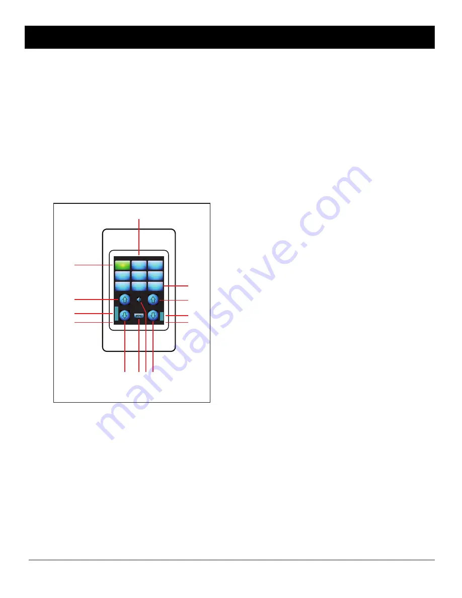
5.2.4 Screen Layout Guide
Fig 5.3 shows the layout of the A 4491/92 LCD.
LOCAL VOL
ZONE VOL
55
40
ZONE1
INPUT 1
INPUT 2
INPUT 2
INPUT 4
INPUT 5
INPUT 6
INPUT 7
INPUT 8
LOCAL
INPUT
1
2
4
5
6
7
8
9
10
11
13
3
12
5.2.3 DIP Switch Settings
On the rear of the wall plate as shown in Fig 5.2 there are four DIP switches which setup some of the plates options.
Switch 1
ON - PIN is required for access to the menu function.
OFF - PIN not required
Switch 2
ON - Backlight toggles on and off when buttons on screen pressed.
OFF- Backlight doesn’t change when buttons pressed.
Switch 3
Not Used
Switch 4
Not Used
Fig 5.3


