background image

American-Lincoln Technology

          1-43

ATS 46/53 Troubleshooting Guide

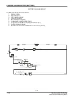
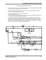
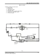
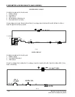
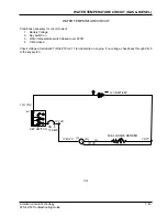
WATER TEMPERATURE CIRCUIT (GAS & DIESEL)

WATER TEMPERATURE CIRCUIT

Conditions necessary for circuit to work

1.

Battery Voltage

2.

Key switch on

3.

Water temperature switch closed (over 220F)

4.

CB-5 closed

Check voltage at terminal #7 (Wire #18) on 11 terminal strip on engine, if no voltage, check back through CB-5
to the key switch.

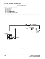
12V BATTERY

4

12,12A

7X,7Y

12B,12C

15

7D,7E

1,1A,1D,9

(I)

(S)

(G)

FG

FUEL GUAGE SENDER

KEY SWITCH

CB -5

15 AMP.

BAT.

T115

Содержание ATS 46

Страница 1: ...ITY QUALITY QUALITY QUALITY QUALITY QUALITY QUALITY QUALITY QUALITY QUALITY QUALITY QUALITY TOTAL TOTAL TOTAL TOTAL TOTAL TOTAL TOTAL TOTAL TOTAL MANAGMENT TOTAL QUALITY TOTAL TOTAL QUALITY TOTAL TOTA...

Страница 2: ...UIT WITH MORE THAN 4 35 PSI GAS 1 22 CRANKING CIRCUIT WITH MORE THAN 2 8 PSI DIESEL 1 23 RUN CIRCUIT GAS 1 24 RUN CIRCUIT DIESEL 1 25 GOVERNOR CIRCUIT GAS 1 26 GLOW PLUG CIRCUIT DIESEL 1 27 SHAKER MOT...

Страница 3: ...tches off 7 Do not dump the hopper over an open pit or dock Do not dump the hopper when positioned on a grade ramp The machine must be level horizontal 8 Operate only when lids doors and access panels...

Страница 4: ...ictions hoses valves cylinders pumps and motors transmitting torque measurement of flow and pressure drop between two points in a hydraulic circuit the amount of power used between these points may be...

Страница 5: ...n 85 10 RPM Standard Scrub Heavy Scrub 185 10 RPM 180 10 RPM Scrub Brush Speed Auxiliary Pump Pressure Main Broom On is Sweep Position Main Broom On in Float Position Normal Scrub On Only Heavy Scrub...

Страница 6: ...0 to 15000 RPM Range EXTECH model AC461893 or equivalent 3 Reflective Tape for use with photo tachometer EXTECH model AC461935 or equivalent 4 Flowmeter 0 5 to 4 GPM Range HEDLAND model 600 004 or equ...

Страница 7: ...rtridge 7 Inspect main manifold relief cartridge RV1 O rings for damage and replace O rings as required Hold the dump door lever in the open position and measure the pressure at the auxiliary pump The...

Страница 8: ...replace motor s If the speed is 50 rpm or below the normal minimum operating speed see Main Broom Slow Troubleshooting section Scrub deck drifts down 1 Damaged solenoid valve 2 Damaged deck cylinder 1...

Страница 9: ...V4 and SV5 and repair or replace the cartridges as required If the solenoid valves appear functional and the condition remain replace the check valve CV1 If the condition remains after the above effor...

Страница 10: ...WER should read 200 25 PSI is below 175 PSI inspect the Squeegee will not lower 1 Low hydraulic oil level 2 Squeegee obstructed 3 Low hydraulic oil level 4 Squeegee obstructed 5 Damaged valve and or c...

Страница 11: ...rear of the machine and place on jack stands such that the rear wheel clears the floor Start the machine and operate the steering wheel If the pressure gauge reads more than 400 PSI while steering exc...

Страница 12: ...the belt driven pump is below 1500 PSI adjust the relief valve in the squeegee vacuum motor If the maximum pressure reading to the output of the auxiliary pump is below 2500 PSI adjust the relief mani...

Страница 13: ...INDER CYLINDER CONTROL VALVE HOPPER LIFT CYLINDER CHECK VALVE HOPPER CONTROL VALVE RETURN VALVE BLOCK MAIN CONTROL VALVE WHEEL DRIVE MOTOR 158 RPM 18 CIR OPTIONAL OIL COOLER VAC FAN MOTOR 453 CIR WET...

Страница 14: ...R SCRUB L H WHEEL DRIVE MOTOR STEERING UNIT 158 RPM 18 CIR 65 PSI 4 5 CIR MOTOR BROOM MAIN RPM ENGINE 2050 9 05 GPM 3500 PSI 3500 PSI CIR PUMP 1 35 PISTON AUX CHARGE 40 CIR PUMP 1 02 CIR 12 27 GPM MAX...

Страница 15: ...885 092 7 88 00094 7 88 00069 8 88 00053 8 88 00064 8 17 05022 8 17 05029 7 17 05011 7 17 05011 7 17 05019 7 17 05010 7 24 04031 8 60 05034 8 24 04115 8 62 01010 Seal Kit Seal Kit Seal Kit Seal Kit Se...

Страница 16: ...rod end of the scrub deck cylinder and maintains the raised position of the scrub deck When SV2 is energized oil may flow both directions between SV3 and port C1 This allows oil trapped in the rod en...

Страница 17: ...rols return oil from port C4 and serves as the squeegee lock valve P N 7 12 02007 When SV6 is not energized oil may flow from SV4 to port C4 but nor in the opposite direction This traps oil in the bas...

Страница 18: ...V1 is not energized SV1 is open and allows bypass oil from FR1 to flow to SV2 This is the main broom and dust control OFF position When SV1 is energized SV1 is closed and the direct path to SV2 is blo...

Страница 19: ...2 Under normal operation oil pressure remains below 2 500 PSI at port 1 and RV1 remains closed When 2 500 PSI is achieved at port 1 RV1 opens and permits oil to flow directly to port T1 and back to ta...

Страница 20: ...l troubleshoot ing should be done by a qualified technician experienced in DC voltage and DC testing equipment GENERAL STATEMENT The following guide will present each electrical circuit separately not...

Страница 21: ...und on 2 of the electronic governor and 1 on 11 terminal strip 12V BATTERY M5 16 2B 2 3 2A 2B 3A 3D 12 12A 2A 9A 14 14A 14 39 39 40 41 RED BLK 42 8 54 54 8 3C 40 7M 7N 3D 7 7M 7Y 7Z 1 1A 1D 9 M1 OP SW...

Страница 22: ...on 11 term strip on engine 7 Battery voltage on engine speed switch and Blue lead on run solenoid 8 Good ground on the run solenoid Orange Wire 12V BATTERY M6 8 M1 R OP SW M3 M3 M1 CB 3 KEY SWITCH CB...

Страница 23: ...r 8 Good ground on 2 of the electronic governor and 1 on 11 terminal strip 12V BATTERY M5 16 2B 2 3 2A 2B 3A 3D 12 12A 2A 9A 14 14A 14 39 39 40 41 RED BLK 42 8 54 54 8 3C 40 7M 7N 3D 7 7M 7Y 7Z 1 1A 1...

Страница 24: ...n 11 term strip on engine 7 Battery voltage on engine speed switch and Blue lead on run solenoid 8 Good ground on the run solenoid Orange Wire 12V BATTERY M6 8 M1 R OP SW M3 M3 M1 CB 3 KEY SWITCH CB 3...

Страница 25: ...round on terminal 1 is good check electronic governor engine speed switch as well as the throttle actuator wiring REG LIGHT TERM 12V BATTERY PART OF ENGINE WIRING PART OF ENGINE WIRING B 3 2 5 1 17 17...

Страница 26: ...als 4 6 on 11 term strip on engine 7 Battery voltage on engine speed switch and Blue lead on run solenoid 8 Good ground on the run solenoid Orange Wires 12V BATTERY M3 KEY SWITCH CB 3 CB5 ARE 15 AMP C...

Страница 27: ...ed to the actuator without also being applied to terminal 1 or damage will result KEY SWITCH IGNITION POSITION IDLE SPEED PIN 8 PIN 7 PIN 6 PIN 5 PIN 4 PIN 3 PIN 2 PIN 1 3 29 VDC BATTERY VOLTAGE BATTE...

Страница 28: ...t at the glow plugs Wire 36 and check for battery voltage if none check M6 If there is voltage on Wires 1D 1E but not on Wire 36 then M6 is not closed Check for battery voltage at the coil of M6 Wire...

Страница 29: ...there is on 30 of M2 then check 86 on M2 M2 86 only gets voltage through TD 1 this 20 sec timer gets voltage from pin 1 to pin 6 when pin 3 is pulsed by the shaker motor switch If no voltage on pin 1...

Страница 30: ...Hopper Down 7 Hopper Door switch 1 closed Hopper Door closed 8 Shaker motor switch momentary closed Pulsed 36V BATTERY 0775 168 0775 166 27 M2 28 MTR SHAKER 77R 1A 1B CB 4 15 AMP BATT 1A 1C IGN 2 3 3B...

Страница 31: ...r way back through main broom switch CB 6 to key switch For side broom start at solenoid 5 then work your way back through side broom switch main broom switch and CB 6 to key switch Note When main bro...

Страница 32: ...tch closed 7 Side broom switch closed 8 Solenoids 4A and 5A energized and contacts closed 36 V BATTERY 0775 166 0775 166 MAIN BRM MTR SIDE BRM MTR 16 17 4A 5A P 19 CB 12 25 AMP CB 13 15 AMP MTR MTR 54...

Страница 33: ...e One of the Wires That Start With The 1 and the ground side Wires That Start With 7 If no voltage is present on the hot side and the ground circuit checks out check back through the light switch to t...

Страница 34: ...circuits to work 1 Battery Voltage 2 Light switch closed 3 Fuse in light switch good closed HEAD TAIL LIGHTS BATTERY 36V BATTERY BANK 7 7J 7P 7Q 7R 7S 7T 7V 7Z 7AM 1 1A 1B BATT IGN ACC 1D WL SW KEY SW...

Страница 35: ...switch works like this 1 Squeegee switch TOP position Squeegee up vac off 2 Squeegee switch MIDDLE position Squeegee up vac on 3 Squeegee switch BOTTOM position Squeegee down vac on SQUEEGEE VACCUM C...

Страница 36: ...position 8 Squeegee switch in LOWER position 9 Squeegee down limit switch closed until squeegee in full down position 10 M100 not energized closed SQUEEGEE CIRCUIT BATTERY 12A 30 C NC 7F 7G 730 DWN LI...

Страница 37: ...Hopper Down 7 Hopper Door switch 2 closed Hopper Door full open 8 Dust control switch closed 9 Main Broom switch closed Main Broom not in full up position 0775 166 0775 166 N P VAC MTR MTR CB 1 25 AM...

Страница 38: ...he squeegee switch M100 when energized stops the squeegee actuator from lowering by de energizing solenoid 12A thus allowing for double scrub When the squeegee switch is in the UP or Middle M100 uses...

Страница 39: ...d 9 holds brush deck up and off when engine is turned off With neutral switch in Neutral brushes will shut off after 2 seconds Bush pressure switch closed energizes solenoids 6 8 12V BATTERY KEY SWITC...

Страница 40: ...ub Deck Down 6 Neutral switch in either FWD or REV 7 TD 2 is de energized 0775 166 0775 166 D 7H SCRUB DECK ACTUATOR YEL 43 42 RED MTR BRUSH MTRS MAIN BRM MTR C C C C C C MTR MTR MTR TOP TERMINAL A 8A...

Страница 41: ...ck Terminal 87A on M3 Wires 3A 3B on back through CB 4 to the key switch HORN CIRCUIT Conditions necessary for circuit to work 1 Battery Voltage 2 Horn switch depressed 3 CB 2 closed Check for voltage...

Страница 42: ...TS BATTERY HORN HOUR AND CONDITION METER CIRCUITS Conditions necessary for circuits to work 1 Battery voltage 2 Key switch on 3 CB 2 and CB 5 closed 4 Horn button depressed for horn only HORN SW 36V B...

Страница 43: ...ircuit to work 1 Battery Voltage 2 Key switch on 3 CB 5 closed 4 Good fuel gauge sender 5 Good ground on fuel gauge meter Check for voltage at I terminal on meter if voltage is not present then check...

Страница 44: ...for circuit to work 1 Battery Voltage 2 Key switch on 3 Water temperature switch closed over 220F 4 CB 5 closed Check voltage at terminal 7 Wire 18 on 11 terminal strip on engine if no voltage check...

Страница 45: ...or circuits to work 1 Battery Voltage 2 Key switch in on 3 CB 3 and FU2 closed 4 Solenoid 1A closed 36V BATTERY 0775 166 0775 166 1 BATT IGN ACC KEY SW 3B 3C 3C 55 7M VAC MTR MTR 7A 7A 50 51 15 AMP CB...

Страница 46: ...o work 1 Battery Voltage 2 Key switch in on 3 CB 8 and CB 14 closed 4 Solenoid 7A closed 5 Squeegee Switch in Middle or Lower Position 0775 166 0775 166 M1 77F G SECONDARY MTR 4 HP MTR M2 1A G FU2 140...

Страница 47: ...TTERY 1 33 HEAD TAIL SWITCH LIGHTS GAS DIESEL 1 32 HOPPER VACUUM CIRCUIT BATTERY 1 36 HORN HOUR AND CONDITION METER CIRCUITS BATTERY 1 41 HOUR METER HORN CIRCUITS GAS DIESEL 1 40 HYDRAULIC SCHEMATIC A...

Отзывы: