1.
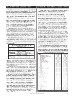
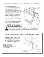
Disconnect the unit from the power source.
2.
Lift hood glass up to access the outer top.
3.
Position the platform mounting bracket in the desired
location along the upper rear edge on the outer top,
making sure that the bracket is tight against the bend in
the top. Using the bracket as a template, mark and
punch six mounting holes in the outer top. Drill these six
holes with a No. 21 drill, and tap with a 10-32 UNF thread.
4.
Attach the scale shelf assembly to the outer top using the
six 10-32x1/2" slotted truss-head screws provided (Alto-
Shaam part number
SC-2661).
5.
Remove the four nuts from the bottom of the platform.
Mount support (bracket provided) to platform using
screws as a guide. While pushing up on support, mark
two mounting holes on the support.
6.
Remove the support. Drill these mounting holes with a
No. 21 drill and tap with a 10-32" UNF thread. Replace
support and mount to unit with the two 10-32x1/2" screws
provided (Alto-Shaam part number
SC-2661).
Replace
nuts on platform bottom and tighten support to platform.
7.
Apply a silicone bead to all perimeter meeting surfaces
between the mounting bracket and the outer top.
NOTE: These platforms are intended for use in the CLOSED
position ONLY. They slide away from the unit for
cleaning. Using scales with platforms in the
OUT position may result in incorrect data on scales.
The scale shelf platform can be removed from the mounting bracket assembly by removing the 10-32
screw/stop located on the bottom of the scale shelf. Removing the screw allows the shelf to be slid
past, and lifted off the shelf guide pins. Failure to replace this screw prior to use could result in
serious bodily injury, and/or damage to equipment.
I NSTALLATION I NSTR UCTIONS — C USTOM ER H EAT G UAR D
D
O N O T O V E R T I G H T E N
!
D
O N O T U S E T H R E A D
T I G H T E N I N G C O M P O U N D S S U C H
A S
"
L O C K T I T E
" .
1.
Lift hood glass up. Remove the 6-32 x 1" screws
for draft strip located on the lower front of the
case.
2.
Align the holes in the plexiglas heat guardwith
the holes of the draft strip. Secure in place with
6-32 x 1" screws provided. Tighten securely
.
I NSTALLATION I NSTR UCTIONS — OPTIONAL SCALE PLATFOR M
Operation and Care Manual #881-3
P g . 7
Содержание ED-48/P
Страница 5: ...Operation and Care Manual 881 3 Pg 4 ...
Страница 6: ...Pg 5 Operation and Care Manual 881 3 ...
Страница 11: ...Operation and Care Manual 881 3 Pg 10 ...
Страница 12: ...Operation and Care Manual 881 3 Pg 11 ...
Страница 14: ...Operation and Care Manual 881 3 Pg 13 ...
Страница 16: ...Operation and Care Manual 881 3 Pg 15 ...
Страница 18: ...Operation and Care Manual 881 3 Pg 17 ...
Страница 19: ...Operation and Care Manual 881 3 Pg 18 ...
Страница 21: ...Operation and Care Manual 881 3 Pg 20 ...
Страница 23: ...Operation and Care Manual 881 3 Pg 22 ...
Страница 24: ...Operation and Care Manual 881 3 Pg 23 ...
Страница 25: ...Operation and Care Manual 881 3 Pg 24 ...
Страница 26: ...Operation and Care Manual 881 3 Pg 25 ...
Страница 27: ...Operation and Care Manual 881 3 Pg 26 ...
Страница 28: ...Operation and Care Manual 881 3 Pg 27 ...
Страница 29: ...Operation and Care Manual 881 3 Pg 28 ...
Страница 30: ...Operation and Care Manual 881 3 Pg 29 ...
Страница 31: ...Operation and Care Manual 881 3 Pg 30 ...
Страница 32: ...Operation and Care Manual 881 3 Pg 31 ...

