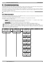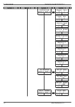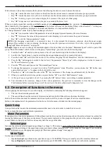
Installation
Instruction manual 91/104 V9.2
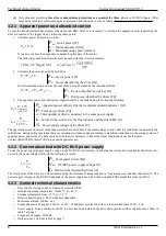
Drawing 14
Connecting a
PLC
to send commands to the digital inputs of the
drive.
The digital outputs of the PLC must provide a voltage of 24Vcc.
It is necessary to connect the 0V of the PLC with the D0V of the
drive.
The 24Vcc power supply can be supplied by the drive itself (if the total current absorbed by the loads connected to the outputs does
not exceed 100mA): connect D24 with clamp +24V (X9) and D0V with A0V clamp (X12).
If the internal power supply cannot be used, an external power supply must be used.
4.4.11 Connector X14
Transducer connection to the optional "Transducer Board“ card. Pin assignment is variable depending on the type of card used and
therefore reference is made to the paragraph relating to the mounted card (see "Optional transducers“ from page 59.
4.5 Commands starting sequence
Please refer to the connectors Connector X9 on page 16 and Connector X12 page 19.
1. Give 230Vca service power supply on the X10 connector.
2. In the case of
model PWM3D-000
when the DOK output switches to ON status and the green LED DOK turns on, you can
give the three-phase/monofase power supply on the terminals L1, L2, L3 or D.C. power supply on the DC-BUS if this mode
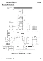
has been selected (see Drawing 2 on page 12 and menu "Power supply from“ on page 57).
In the case of
model PWM3D-010
when the DOK output switches to ON status and the green LED DOK turns on, you can
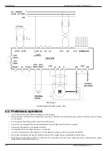
enable the DC-BUS power supply to generate the DC voltage at DC+ and DC- terminals.
After the charge of the capacitors on the DC-BUS, the RDY output switches to ON status. If all the necessary parameters
have been inserted and the autotune has been completed,
the green RDY LED lights up
. From this point the drive is
ready
to
be enabled for operation.
3. When the RDY output switches to ON status, you can enable the drive with the DEN command.
4. When the drive is enabled and works regularly, the green RUN LED is switched on and the DOK and RDY outputs remain in
the ON state and it is possible to give the speed reference resulting in motor rotation.
4.6 Commands shutdown sequence
Please refer to the connectors Connector X9 on page 16 and Connector X12 page 19.
1. Bring the speed reference to 0V and wait until the motor is stationary or alternatively you can use the "DEN" command to
stop the motor if the "Drive Stop/Run“ function has been activated (see page 67). When the motor is stationary it is signalled
on the selected output (normally it is the DO1 output) leading to the ON state and turning on the associated green led.
2. Deactivate the drive (DEN command = OFF). The green RUN LED goes off.
3. Remove the three-phase/monophase power supply (L1, L2, L3) or the D.C. power supply on the DC-BUS. The RDY output
is brought into the state of OFF and the green LED RDY turns off.
4. Remove the 230Vac service power supply (if necessary).
NOTE:
During normal motor gear-stop operation
,
it is recommended to act only on the speed reference (or on the “Stop motor " con-
trol) and on the enable command (DEN) to avoid unnecessary waiting times due to the charge of capacitors on the DC-BUS. Remove
power supply only when you want to stop the motor safely.
4.7 Restarting after an alarm
When the drive enters alarm status (DOK output = OFF and flashing of the red led FLT) it behaves as if suddenly lacked the enable
command (DEN = OFF), then the motor of the motor becomes free and is dragged by the load. It is therefore advisable to provide for
a mechanical braking system if this situation could cause danger. If you have an alarm when the drive is enabled regularly, the DOK
output goes to the OFF state, flashes the red FLT LED and the alarm message appears on the LCD display. When the control system
(PLC or CNC) detects this alarm state, the following sequence shall be performed:
1. Immediately remove power supply (on L1, L2, L3 or DC+, DC-) and drive enable command (DEN = OFF).
2. Detect and whether it is possible to eliminate the cause that generated the alarm.
3. Reset the alarm with the digital input (RST = ON) or by pressing one of the buttons on the front.
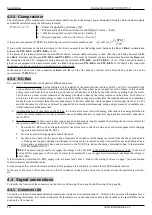
4. Repeat the sequence of starting commands (page 20).
20
Alter Elettronica s.r.l.


