Installation
Instruction manual 91/104 V9.2
6
A0V
0V analog. The analog 0V is connected to the drive case.
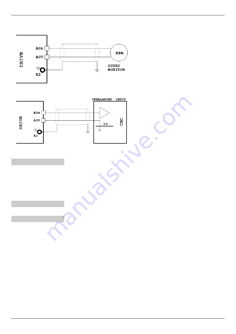
Below are some sample drawings for a correct use of the various signals on X6.
Analog output connection (±10Vcc) to a
speed
indicator tool.
Analog output connection (±10Vcc) to CNC
analog
input
(or a PLC) to detect motor speed.
4.4.5 Connector X7
Connector prepared for connection between two drives in "anti backlash" mode (see section ”Anti-backlash system“ from page 71).
Signal allocation to PINs:
1
T1
Resistance Bus termination value 110 Ω
.
2
T2
3
L
Connecting cable “L” pole
4
H
Connecting cable “H” pole
4.4.6 Connector X8
Connector for optional communication cards.
4.4.7 Connector X9
Connect digital outputs.
Power supply voltage from l8Vcc to 30Vcc (nominal 24Vc.c.)
States of exits:
Off = Floating
On = Connected to +24V power supply (D24) (marked by the lighting of the corresponding led)
Maximum current for each output 100 mA, voltage drop inside the maximum current 2V.
Without service power all outputs are OFF.
In case of overload or short circuit on one or more outputs, all outputs are permanently forced into the OFF state.
For connections please refer to Drawing 6 and Drawing 7 from page 17.
Signal allocation to PINs:
1
DOK
Digital output ”Drive OK”. It indicates that there are no alarms that prevent the drive from working and that it has fin-
ished the peripheral initialisation phase.
Further information can be found in paragraph ”Alarm messages“ on page 77.
2
RDY
“Ready“ digital output. It signals that the drive is ready for operation and is therefore able to perform the commands.
See also paragraph ”RDY (Ready)“on page 76.
16
Alter Elettronica s.r.l.
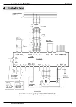
Drawing 4
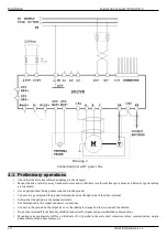
Drawing 5


