Instruction manual 91/104 V9.2
Installation
3
DO1
Digital output 1 programmable.
It is normally used to signal ”Zero Speed“ i.e. that the motor is stationary.
4
DO2
Digital output 2 programmable.
It is normally used to signal the achievement of a speed threshold.
5
DO3
Digital output 3 programmable.
Normally it is used to report that the motor load is more than 90 % (see page 66)
6
DO4
Digital output 4 programmable.
It is normally used to report that the motor position has been reached (see page 74)
7
D24
Common to connect to +24Vcc for digital outputs.
8
+24V
24Vcc
±20 % – 100mA max.
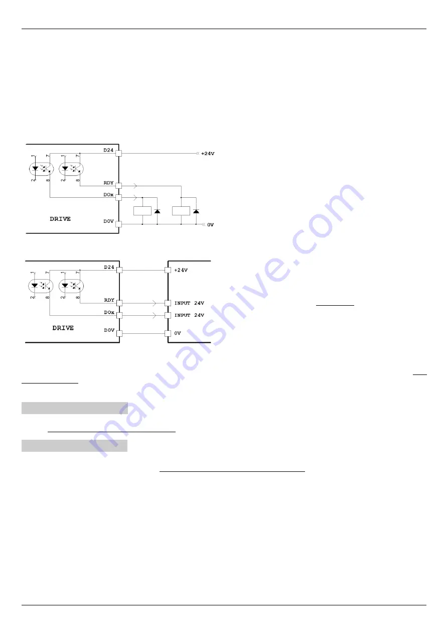
Below are some drawings to explain the correct connections to the X9 connector:
Relay connection to receive signals from the digital outputs of the
drive.
It is necessary to connect the D24 to a power 24Vcc and
the D0V to 0V.
Connection of a
PLC
to receive signals from the drive.
The digital inputs of the PLC must receive a voltage of 24Vcc.
It is necessary to connect the PLC +24V power supply with the
D24 of the drive and the 0V of the PLC with the D0V of the
drive.
The 24Vcc power supply can be supplied by the drive itself (if the total current absorbed by the loads connected to the outputs does
not exceed 100mA): connect D24 with clamp +24V (X9) and D0V with A0V clamp (X12).
If the internal power supply cannot be used, an external power supply must be used.
4.4.8 Connector X10
Power connection auxiliary services 230Vac 500mA (Max). Mount protective fuses with 1 retarded amperes. The power supply of the
services MUST be present before the power supply and must not be removed before the power supply.
4.4.9 Connector X11
Connection reference voltages and analog inputs.
Always use good quality shielded cables and connect the two ends of the shield to the ground. On the drive case, near the connectors,
anchorages are available for shields (see Mechanical characteristics page 85).
Signal allocation to PINs:
1
+24V
24Vcc
±20 % – 100mA max.
2
+10V
10Vcc
±5 % – 5mA max.
3
-10V
Output -10Vcc
±5 % – 5mA max.
4
AI1+
Main analog input hot pole 1 (resolution 15 bit + sign) programmable which is normally used for speed reference.
Tensions between: AI1+ and A0V, AI1- and A0V, AI1+ and AI1- = ±10V max. 10KΩ input resistance.
5
AI1-
Cold pole of the analog input 1.
6
A0V
0V analog. The analog 0V is connected to the drive case.
7
AI2
Analog input 2 (resolution 11 bit + sign) programmable. Voltage between AI2 and A0V = ±10Vcc max.
Alter Elettronica s.r.l.
17
Drawing 6
Drawing 7


