manualshive.com logo in svg
background image

10

Operating Manual -4048A digital signal processor

7.3 Audio Functions

Editing of audio controls is done through the use of scroll bars, numerical entry, various keyboard shortcuts,

or by visually dragging filter points in the frequency response window.  Ease of use, especially in the frequency
response window, makes it possible for fast, potentially destructive mistakes, so plan carefully before making radical
gain or filter changes.

7.3a Keyboard/Mouse Shortcuts

Convenient shortcuts allow for quick setups or edits, and are shown as follows:

Mouse shortcuts in the frequency response window . . .

Right Click-and-Drag

Change Q-Width

Left Click-and-Drag

Change Frequency

Left Click-and-Drag

Change Level

Keyboard shortcuts . . .

i

Change to last input used

o

Change to last output used

s

Change the order in which parametric and crossover filters are scanned

d

Change to the Delay frame

g

Change to the Gain frame

e

Change to the EQ frame

r

Change to the Routing frame

h

Change to the HpfLpf frame

l

Change to the Limiter frame

m

Mute the current input or output channel

ESC(while dragging a filter)

Resets the filter position to its starting position

c

Cut Active Filter

z

Zero Active Filter

Ctrl-c

Cut Master Gain

Ctrl-z

Zero Master Gain

7.3b  Mute

The 4048A allows the user to mute all inputs or outputs.  When muted, an input or output's red Mute LED is lit.

To mute or unmute all outputs simultaneously, click on the <Mute> menu heading and select the <Mute all> or <Unmute
all> option.  Inputs can be muted or unmuted one at a time.  Additionally, when recalling a new preset to the 4048A, the
user is prompted to mute all outputs, as a new preset can introduce dramatic changes to the system configuration.
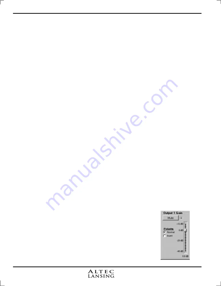
7.3c  Gain

For best signal to noise performance, provide an input signal with a nominal 0dBu

level.  Using significant input or output gain to make up for a weak input signal compromises
the noise performance of the 4048A.

Input and Output Gain are separately adjustable from -40dB to +12dB.  Due to limi-

tations within the graphical interface, fine tuning gain settings in 0.1dB steps is accomplished
using the <up/down arrows> on the keyboard.  Changes of exactly 1dB are quickly accom-
plished using <PageUp/PageDown> buttons.  To instantly return a gain setting to 0dB, press
<Ctrl + Z> (see other keyboard shortcuts in 7.3a)
.  Additionally, The output gain menu is also
used to invert the polarity of outgoing signal for that channel.

Содержание 4048A SIGNAL PROCESSING

Страница 1: ...c Lansing Pr Altec Lansing Pr Altec Lansing Pr Altec Lansing Professional ofessional ofessional ofessional ofessional 1000 W Wilshire Blvd Suite 362 Oklahoma City OK 73116 USA A division of Altec Lansing Technologies Inc Milford PA 18337 0277 Made In USA ...

Страница 2: ...O TEC LANSING MAESTRO TEC LANSING MAESTRO SOFTW SOFTW SOFTW SOFTW SOFTWARE ARE ARE ARE ARE 8 7 7 7 7 7 GETTING ST GETTING ST GETTING ST GETTING ST GETTING STA R A R A R A R A RTED TED TED TED TED 9 8 8 8 8 8 OTHER SOFTW OTHER SOFTW OTHER SOFTW OTHER SOFTW OTHER SOFTWARE FUNCTIONS ARE FUNCTIONS ARE FUNCTIONS ARE FUNCTIONS ARE FUNCTIONS 15 9 9 9 9 9 TROUBLESHOOTING TIPS TROUBLESHOOTING TIPS TROUBLES...

Страница 3: ...to alert the user to the presence of uninsulated dangerous voltage within the product s enclosure that may be of sufficient magnitude to constitute a risk of electric shock to persons TO REDUCE THE RISK OF ELECTRIC SHOCK DO NOT REMOVE COVER NO USER SERVICEABLE PARTS INSIDE REFER SERVIC ING TO QUALIFIED SERVICE PERSONNEL TO REDUCE THE RISK OF FIRE OR ELECTRICAL SHOCK DO NOT EXPOSE THIS APPlIANCE TO...

Страница 4: ...ess appearance After unpacking please inspect for any physical damage Save the shipping carton and all packing materials as they were carefully designed to minimize the possibility of transportation damage should the unit again require packing and shipping In the event that damage has occurred immediately notify your dealer so that a written claim to cover the damages can be initiated The right to...

Страница 5: ...D becomes lit when an output channel is turned off through software control 4 3 Preset Indicator This display indicates the currently selected preset number 1 18 for the 4048A This display also indicates the following operating conditions within the 4048A Firmware revision number is displayed during power up and when a factory reset is aborted Factory reset countdown which occurs by pressing and h...

Страница 6: ...ut trim adjustments on the 4048A therefore all the processing including gain is done in the digital domain As a consequence of this design philosophy it is important to feed the processor with the proper nominal signal level to achieve good signal to noise performance as well as headroom before clipping The 4048A is designed to clip at signal levels above 20dBu 7 75Vrms which places the noise floo...

Страница 7: ...es may be used where the trigger event is the transition from open to closed for a given circuit Closing a circuit will automatically override any previously recalled presets Up to eight switches can be used with all switches sharing a common ground connection Each pin number above the contact closure connector corresponds to the number of the preset which will be recalled when that switch is clos...

Страница 8: ...computer A standard D Sub nine pin female to male connector cable is used to connect the PC to the 4048A If the PC lacks a nine pin RS 232 port an active USB to RS 232 converter can be purchased at computer stores Following are the suggested steps for connecting the 4048A to a PC 1 Plug the RS 232 cable into an available serial port on the PC 2 Plug the other end of the cable into either the front...

Страница 9: ...the Options menu The default configuration options are 1 4 x 2 way Crossover 2 2 x 3 way and 2 Aux 3 2 x 3 way mono sub 4 2 x 4 way Crossover 5 1 x 5 way and 3 Aux 6 Mono Distribution 7 Stereo Distribution 8 LCRS with mono subs 9 4 x 4 Processor 10 Muted Flat Start up 7 2 Metering Options The front panel LEDs on the 4048A indicate signal present 20dBu 0dBu inputs only or clip 20dBu For more detail...

Страница 10: ... filter position to its starting position c Cut Active Filter z Zero Active Filter Ctrl c Cut Master Gain Ctrl z Zero Master Gain 7 3b Mute The 4048A allows the user to mute all inputs or outputs When muted an input or output s red Mute LED is lit To mute or unmute all outputs simultaneously click on the Mute menu heading and select the Mute all or Unmute all option Inputs can be muted or unmuted ...

Страница 11: ...ctory default is 1kHz but each filter s center frequency is adjustable from 19 7Hz to 21 9kHz in 1 96 octave steps Carefully sweeping a narrow bandwidth filter through a problem feedback area with just a slight boost is a quick way to find the exact frequency causing trouble Once the offensive frequency has been found cut the filter s level and then adjust the bandwidth as narrow as possible while...

Страница 12: ...aking it necessary for the user to map out ahead of time which outputs will be used for the various frequency bands and set the overlapping filter frequencies and types accordingly Note The HPF determines the lower frequency limit of the signal while the LPF determines the upper frequency limit The frequency range for the high pass filter HPF is from 19 7Hz to 21 9kHz with an option to turn the fi...

Страница 13: ...B oct Bessel filters One of the outputs must be inverted when using either 12dB oct or 18dB oct Bessel crossover filters or else the combined response will have a large notch Linkwitz Riley The 12 dB oct and 24dB oct Linkwitz Riley filters individually are always 6dB at the displayed crossover frequency however the 18dB oct Linkwitz filters individually are always 3dB at the displayed crossover fr...

Страница 14: ...osest to the cluster front Using the location of the driver diaphragm farthest back as a reference point measure the distance to other drivers in the cluster and set the output delay for each accordingly with the driver diaphragm closest to the front getting the longest delay and the driver at the very back getting no delay at all The minimum adjustment is 0 02 milliseconds or about inch When appr...

Страница 15: ... configurations repeat ing two times A preset file contains the control parameters of all four inputs and eight outputs For a written record of all parameters of a specific preset file click Print Channel in the File menu Since there are no user controls on the 4048A the only way to load channel presets is by using Altec Lansing Software to recall files saved on either the PC or the 4048A The exce...

Страница 16: ...cated by a lower case r in the display followed by normal operation of the unit 9 TROUBLESHOOTING 9 1 Audio Troubleshooting Tips 1 No power Is the detachable AC cord fully plugged in Is the rear panel power switch on 2 Software controls don t work Is the RS 232 cable properly installed to the PC Is the software commu nications enabled Is the correct Comm port selected Check the security level sect...

Страница 17: ...Boost Cut Range 15dB 30dB Parametric Filter Frequency Range 19 7Hz to 21 9kHz 1 96 Octave Steps Parametric Filter Bandwidth Four Octaves to 1 64 Octave All pass phase shift 0 deg at low freq 180 deg at selected freq 360 deg at high freq Delay Output Delay 0 682 milliseconds Crossover HPF and LPF Frequency Range 19 7Hz to 21 9kHz Off Available Filter Types 12dB Oct Butterworth 12dB Oct Bessel 12dB ...

Страница 18: ...technical services at 405 848 3108 Fill out the information below for your records Serial Number______________ Dealer _______________________ Date of Purchase ___________ Dealer s Address _______________________________________________ Dealer s Phone _____________ Salesperson ____________________________________________________ Altec Lansing 4048A Digital Signal Processor 6 00 152 0 00 0 25 6 4 18...

Страница 19: ...24dBLinkwitz Output Delay Output Gain Phase Invert Output Limiter Output Mute Limiter Threshold LED Software Output Meters D A Output Channels 1 8 Route Input Channels A D To Output Channels 1 8 in Any Combination Routing Limiter Link A 1 B Mute Gain EQ Route C Mute Gain EQ Route D Mute Gain EQ Route Altec Lansing 4048A Block Diagram Inputs Outputs Mute Gain EQ Route HpfLpf EQ Delay Gain Limiter M...

Страница 20: ... Altec Lansing Pr Altec Lansing Pr Altec Lansing Pr Altec Lansing Pr Altec Lansing Professional ofessional ofessional ofessional ofessional 1000 W Wilshire Blvd Suite 362 Oklahoma City OK 73116 USA A division of Altec Lansing Technologies Inc Milford PA 18337 0277 Made In USA ...

Отзывы: