background image

5-10

EPAC 3100/3500

GI 1.6882

5.3.

POWER SUPPLY CONNECTIONS

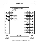
The power supply  PS  is connected to the X6 screw-in connector on the rear panel.  The wire
used must have a section less than 5 mm

2

. See 5.1. and 5.2. for wiring recommandations. Avoid

long distance wirings to DC source (less than 20-30 m) without special care.

X6 Connector

27

- Power Supply

+ Power Supply

28

Figure 5.3a: Power Supply Connections

5.4.

EQUIPMENT FAULT SIGNALLING CONNECTIONS

X6 Connector

9

10

X6 Connector

15

16

Figure 5.4a: Fault Signalling Connections

The equipment fault signal wires are connected to pins 9 and 10 of the X6 terminal block on
the IO-1 Board and to pins 15 and 16 of the X6 terminal block on the additional IO-1 Board
or the IO-2 Board.

5.5.

COMMUNICATION OPTION CONNECTIONS

 The EPAC  can be connected to three types of communication system:

- Communication with an remote control system, either VDEW or KBUS-COURIER.

- Reception of an external time synchronisation signal via an IRIG-B board.

- Communication with the TPE system for disturbance event management. Communication is

by means of:

. a current loop for a link to a UR 2000 restitution unit,

. a Modem for a link to the TPE via the PSTN,

. RS232 for a direct link to the EPAC  via the RS232 serial port on the EPAC front panel.

(ERRATUM)

Содержание EPAC 3100

Страница 1: ...3 3 1XPHULFDO GLVWDQFH UHOD ZLWK LQWHJUDWHG DXWRPDWLF DQG FRQWURO HTXLSPHQW QVWDOOHU V XLGH...

Страница 2: ...EPAC 3100 3500 GI 1 6882 P 2 PAGE NOT USED...

Страница 3: ...artment Avenue de Figui res F 34975 LATTES CEDEX Have you found any errors in the brochure If so please indicate where they are Did you find the brochure comprehensible and well set out Please indicat...

Страница 4: ...perfor mance of his or her tasks The following table summarizes the titles of the documents their recipients and the supply date Document Title Recipient Supply date Installer s Guide Installer of Eq...

Страница 5: ...GI 1 6882 EPAC 3100 3500 P 5 REASON FOR UP DATES GI 1 6882 INSTALLER S GUIDE EPAC 3100 3500 First edition 06 97 Indice Updating Updating subject date...

Страница 6: ...DEX PAGE INDEX STATE OF UP DATES A B C D E F G H I J K L M N P 1 P 2 P 3 P 4 P 5 P 6 P 7 P 8 PRELIMARY PAGES CHAP 1 1 1 1 2 1 3 1 4 CHAP 2 2 1 2 2 2 3 2 4 2 5 2 6 CHAP 3 3 1 3 2 3 3 3 4 3 5 3 6 CHAP 4...

Страница 7: ...3 3 ASSEMBLY __________________________________________________________________ 3 5 CHAPTER 4 ELECTRICAL CONDITIONS __________________________________________________ 4 1 4 1 ELECTRIC POWER SUPPLY ___...

Страница 8: ...EPAC 3100 3500 GI 1 6882 P 8 PAGE NOT USED...

Страница 9: ...GI 1 6882 EPAC 3100 3500 CHAPTER 1 TRANSPORTATION AND STORAGE CONDITIONS...

Страница 10: ...EPAC 3100 3500 GI 1 6882 PAGE NOT USED...

Страница 11: ...___________________________ 1 3 1 2 STORAGE ON SITE OR IN A WAREHOUSE _______________________________________ 1 4 1 2 1 Normal Storage Conditions ____________________________________________________ 1...

Страница 12: ...1 2 EPAC 3100 3500 GI 1 6882 PAGE NOT USED...

Страница 13: ...nd a weight of 100 kg without being deformed You should therefore avoid stacking more than 5 boxes of the same equipment or any other package weighting more than 80 kg on top of it When handling the b...

Страница 14: ...in order to keep the level of humidity inside the envelope at a level lower than 5 g of water per m3 These packages contain dessicant pouches that must be renewed every 6 12 or 24 months depending on...

Страница 15: ...GI 1 6882 EPAC 3100 3500 CHAPTER 2 UNPACKING...

Страница 16: ...EPAC 3100 3500 GI 1 6882 PAGE NOT USED...

Страница 17: ...GI 1 6882 EPAC 3100 3500 CONTENT PAGE 2 1 UNPACKING_________________________________________________________________ 2 3 2 2 REPACKING _________________________________________________________________...

Страница 18: ...2 2 EPAC 3100 3500 GI 1 6882 PAGE NOT USED...

Страница 19: ...Open the flaps by folding them back as shown on the packing diagram 6 Remove the various elements from the cardboard box and check that the contents cor respond to the list given in chapter 1 7 Remov...

Страница 20: ...2 4 EPAC 3100 3500 GI 1 6882 Figure 2 1a Packing Unpacking the EPAC 3100 3500 Superior hand packing block Product Inferior hand packing block Card board base UP DOWN...

Страница 21: ...Put the plastic bags containing the documents and connection kit connectors on the packed rack 6 Fold down the four flaps 7 Staple flaps 8 Use adhesive tape to close the box 9 Clearly indicate the fo...

Страница 22: ...2 6 EPAC 3100 3500 GI 1 6882 PAGE NOT USED...

Страница 23: ...GI 1 6882 EPAC 3100 3500 CHAPTER 3 MECHANICAL CHARACTERISTICS AND INSTALLATION CONDITIONS...

Страница 24: ...EPAC 3100 3500 GI 1 6882 PAGE NOT USED...

Страница 25: ...OVERALL DIMENSION_________________________________________________________ 3 3 3 2 WEIGHT ____________________________________________________________________ 3 4 3 3 ASSEMBLY ________________________...

Страница 26: ...3 2 EPAC 3100 3500 GI 1 6882 PAGE NOT USED...

Страница 27: ...82 EPAC 3100 3500 3 1 OVERALL DIMENSION The overall dimensions of the EPAC 3100 3500 depend on whether it is frame or cabinet mounted 412 50 177 00 304 3 Figure 3 1a Rack dimensions when frame mounted...

Страница 28: ...3 4 EPAC 3100 3500 GI 1 6882 57 1 15 5 88 9 483 0 177 0 304 3 Figure 3 1b Rack dimensions when cabinet mounted EPAC 3500 3 2 WEIGHT 12 kg...

Страница 29: ...e 3 1c The cabinet mounted EPAC 3500 is attached with 4 screws on the left and right of the front panel 412 362 5 24 8 246 116 5 5 2 168 3 Figure 3 1c Location of attachment points for frame mounting...

Страница 30: ...3 6 EPAC 3100 3500 GI 1 6882 PAGE NOT USED...

Страница 31: ...GI 1 6882 EPAC 3100 3500 CHAPTER 4 ELECTRICAL CONDITIONS...

Страница 32: ...EPAC 3100 3500 GI 1 6882 PAGE NOT USED...

Страница 33: ...GI 1 6882 EPAC 3100 3500 CONTENT PAGE 4 1 ELECTRIC POWER SUPPLY______________________________________________________ 4 3 4 2 GROUNDING ________________________________________________________________...

Страница 34: ...4 2 EPAC 3100 3500 GI 1 6882 PAGE NOT USED...

Страница 35: ...ted Variations 20 to 20 20 to 15 for 250 V Power consumption in the basic version 25 W Temperature Range in operation 20 C to 55 C Maximum permitted ripple 12 Relative Humidity less than 95 with no co...

Страница 36: ...he EPAC 3100 3500 rack It is identified by the ground symbol The following diagrams show the grounding braid connections for the different EPAC 3100 3500 options Current loop To UR Protection cable 27...

Страница 37: ...GI 1 6882 EPAC 3100 3500 CHAPTER 5 EXTERNAL CONNECTIONS...

Страница 38: ...EPAC 3100 3500 GI 1 6882 PAGE NOT USED...

Страница 39: ...5 2 INPUT AND OUTPUT CONTACTS CONNECTIONS __________________________________ 5 6 5 3 POWER SUPPLY CONNECTIONS _______________________________________________ 5 10 5 4 EQUIPMENT FAULT SIGNALLING CONNEC...

Страница 40: ...5 2 EPAC 3100 3500 GI 1 6882 PAGE NOT USED...

Страница 41: ...one multiwire 4 to 8 depending on external neutral connection c ble of 4 mm2 for 1 A current circuit or 6 mm2 for 5A current The external diameter of the cables is recommended as less than 15 mm If t...

Страница 42: ...3 ILS2 ILE2 ILS1 ILE1 X5 Connector Figure 5 1a Analog input connections without zero sequence current transformer P1 UL2 UL3 P2 P1 P2 P1 P2 UL1 S1 S2 S1 S2 S1 S2 TMH To BCH UBAR UL1 UL2 UL3 UL1 ULM UL...

Страница 43: ...onnector QTF Board TMH S TMH E U bar U BarE TMH S TMH E U BarS UN UL1 If IN 1A If IN 5A If IN 1A If IN 5A If IN 1A If IN 5A If IN 5A If IN 1A UL2 UL3 INE INS INS INE IL S3 IL E3 IL S3 IL E3 IL S2 IL E...

Страница 44: ...1 5 or 2 5 mm2 for tripping contacts We recommend to use flexible multiwire 9 to 16 depending on number of groups common cable of 0 6 to 1 5 mm2 wire section for input contacts for all pins of the X2...

Страница 45: ...URABLE LOGIC INPUTS TS CONFIGURABLE SIGNALLING CONTACTS TC CONFIGURABLE SIGNALLING CONTACTS TC X1 2 4 6 8 10 12 14 16 18 20 22 24 26 28 X2 2 4 6 8 10 12 14 16 18 20 22 24 26 28 Screw in Connector Scre...

Страница 46: ...C INPUTS TS CONFIGURABLE SIGNALLING CONTACTS TC CONFIGURABLE SIGNALLING CONTACTS TC X3 2 4 6 8 10 12 14 16 18 20 22 24 26 28 X4 2 4 6 8 10 12 14 16 18 20 22 24 26 28 Screw in Connector Screw in Connec...

Страница 47: ...NG CONTACTS TC CONFIGURABLE SIGNALLING CONTACTS TC X3 2 4 6 8 10 12 14 16 18 20 22 24 26 28 X4 2 4 6 8 10 12 14 16 18 20 22 24 26 28 EPAC 3100 3500 Screw in Connector Screw in Connector TC 01 TC 04 TC...

Страница 48: ...nt fault signal wires are connected to pins 9 and 10 of the X6 terminal block on the IO 1 Board and to pins 15 and 16 of the X6 terminal block on the additional IO 1 Board or the IO 2 Board 5 5 COMMUN...

Страница 49: ...Front Panel Option Connections X30 27 1 28 2 27 1 28 2 27 1 28 2 27 1 28 2 27 1 28 2 X2 1 27 2 28 X4 X1 X6 X3 X5 X30 BNC connection for IRIG B time synchronisation signal X18 D25 D24 Current loop and...

Страница 50: ...V DSR RTS CTS D26 connector BNC connector for IRIG B time synchronisation signal X30 connector KBUS Ground Description Terminal Description Terminal D24 connector VDEW receiver D25 connector VDEW tran...

Страница 51: ...GI 1 6882 EPAC 3100 3500 APPENDICES...

Страница 52: ...EPAC 3100 3500 GI 1 6882 PAGE NOT USED...

Страница 53: ...BBBBBBBBBBBBBBBBBB 5 237 211 7 216BBBBBBBBBBBBBBBBBBBBBBBBBBBBBBBBBBBBBBBBBBBBBBBBBBBBBB 6 211 7 21 5 0 3 BBBBBBBBBBBBBBBBBBBBBBBBBBBBBBBBBBBBBBBB 6 211 7 21 5 0 3 BBBBBBBBBBBBBBBBBBBBBBBBBBBBBBBBBBBB...

Страница 54: ...55 780 3 abcd...

Страница 55: ...55 780 3 abcd...

Страница 56: ...55 780 3 abcd 6 211 7 21 5 0 3 3...

Страница 57: ...55 780 3 abcd 6 211 7 21 5 0 3 3...

Страница 58: ...55 780 3 abcd 6 211 7 21 5 0 3 3...

Страница 59: ...55 780 3 abcd 6 211 7 21 5 0 3 3...

Страница 60: ...55 780 3 abcd 3 127 86...

Отзывы: