background image

Alpine TR42 Direct Vent Gas Fireplace 

                                   VENTING  

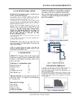
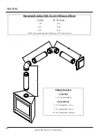
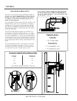
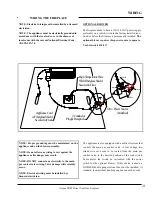
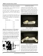
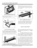
Figure 9 – Clearance to Venting 

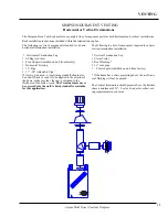
VENTING PLANNING 

The Alpine TR-36 uses Simpson Duravent Co Axial 
venting systems. The inner tube vents products of 
combustion away from the appliance, while the outer tube 
draws outside air into the combustion chamber. This is a 
closed system and uses no air from the interior of the home 
for combustion.  

Never attach this fireplace vent to another vent serving 
another appliance. Each direct vent gas appliance must use 
its own separate venting system. Common venting systems 
are prohibited for use with this appliance.  

Always vent the fireplace to outside of the building. Never 
vent into a garage or enclosed area.  

This venting system, in combination with the Alpine TR-
36 Direct Vent Gas Fireplace, has been tested and listed as 
a direct vent heater by Intertek. The location of the 
termination cap must conform to the requirement in the 
Vent Termination Clearances diagram on page 10 of this 
manual. 

Before proceeding with installation, carefully examine the 
chart on page 10 of this manual for options regarding 
proper placement of the vent termination.  

In all cases, adequate combustion and ventilation air must 
be available for the fireplace. 

Never block the termina-

tion cap.

 Make sure foliage does not grow around the 

termination cap.  In all cases, follow the clearances listed 
on page 8  of this manual.  


NOTE: Never connect this gas appliance to a chimney 
flue serving a separate solid-fuel burning appliance.  


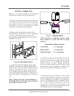
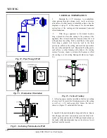
CLEARANCE 

FROM 

VERTICAL 

PIPE TO 

COMBUSTIBLES 

IS 1-1/2" 

CLEARANCE TO 

COMBUSTIBLES ON 

HORIZONTAL PIPE IS                           

2" FROM TOP 

 1 " FROM SIDES                     

1/2" BOTTOM

SIMPSON DURAVENT 

VENTING COMPONENTS LIST 

(4”x6 5/8”)


Stock # 

Description 

46DVA-E45 

45 Degree Elbow 

46DVA-E90 

90 Degree Elbow


46DVA-SC Storm 

Collar 

46DVA-F6 

Standard Flashing   0/12 – 5/12 

46DVA-F12 

Steep Flashing        6/12 – 12/12 

46DVA-WS Wall 

Strap 

09183  

Firestop 

Spacer 

46DVA-16A 16” 

Extension 

46DVA-8A 8” 

Extension 

09382   

17” - 24” Adjustable pipe 

46DVA-12 12” 

pipe 

46DVA-24 24” 

pipe 

46DVA-36 36” 

pipe 

46DVA-48 48” 

pipe 

46DVA-VCH 

Vertical Termination Cap 

46DVA-HC 

Horizontal Termination Cap 

46DVA-DC Wall 

Thimble 

46DVA-SNK14  14” Snorkel Termination Cap 
46DVA-SNK36  36” Snorkel Termination Cap 
09361   

Vinyl Siding stand-off 


Parts not supplied by Simpson 

09362  

Flue 

Adapter 

09364  

Vent 

Guard 

09367   

Horizontal  Firestop 

09301   

Attic Insulation Shield 


Содержание TR42 - LP TAMARRON

Страница 1: ...s of life Improper installation adjustment alteration service or maintenance can cause property damage personal injury or loss of life INSTALLER PLEASE LEAVE THIS MANUAL WITH THE CUSTOMER HOMEOWNER PLEASE KEEP THESE INSTRUCTIONS FOR FUTURE REFERENCE These gas appliances have been tested in accordance with National Safety Standards and have been certified by Intertek for installation operation as d...

Страница 2: ...2 Alpine TR42 Direct Vent Gas Fireplace ...

Страница 3: ...rranty 32 GENERAL INFORMATION Rating Plate 4 Before Starting 5 General Safety Information 5 System Specifications 6 Derating the Burner 6 INSTALLATION REQUIREMENTS Locating the Fireplace 6 Gas Line Installation 7 Clearances 7 Mantel Clearances 7 Hearth Materials 7 Framing and Finishing 8 VENTING Venting Planning 9 Venting Components List 9 Vent Termination Clearances 10 Horizontal Vertical Compone...

Страница 4: ... with air filters Electrical supply 120VAC 3 5 Amps 60Hz This appliance is only for use with the type of gas indicated on the rating plate and may be installed in an aftermarket permanently located manufactured home USA only or mobile home where not prohibited by local codes See owner s manual for details This appliance is not convertible for use with other gases unless a certified kit is used Thi...

Страница 5: ... with local codes or in the absence of local codes with the current National Fuel Gas Code ANSI Z223 1 installation code 2 The appliance when installed must be electrically grounded in accordance with local codes or in the absence of local codes with the current National Electrical Code ANSI NFPA 70 3 This appliance must be connected to the specified vent and termination cap to the outside of the ...

Страница 6: ...urdily constructed platform 3 If the appliance is to be installed on carpeting combustible vinyl tiling or any other combustible surface other than wood flooring a wood panel or metal panel must be installed on top of the existing flooring The panel must extend the full width and depth of appliance 4 The Alpine TR42 fireplace can be installed into many different applications See Figure 1 for examp...

Страница 7: ...t and manifold pressures should be checked using the valve pressure ports on the control valve CLEARANCES IMPORTANT Clearances listed in this manual must be adhered to strictly Failure to maintain these listed clearances of the fireplace and venting system can re sult in a house fire Clearance to Combustibles from Fireplace Spacers 0 Fireplace Floor 0 Ceiling 18 Ceiling Flex Vent 24 Side Mantel Le...

Страница 8: ...the home to prevent cold air infil tration through the fireplace chassis Check with your local building official for any additional local requirements e g vapor barriers drywall Never insulate the fire place itself NAILING TABS MUST BE BENT OUT BEFORE FIREPLACE IS INSERTED INTO FRAMING THERE ARE FOUR NAILING TABS 3 The fireplace is equipped with four nailing tabs which must be bent out before inse...

Страница 9: ...options regarding proper placement of the vent termination In all cases adequate combustion and ventilation air must be available for the fireplace Never block the termina tion cap Make sure foliage does not grow around the termination cap In all cases follow the clearances listed on page 8 of this manual NOTE Never connect this gas appliance to a chimney flue serving a separate solid fuel burning...

Страница 10: ...thin 3 M Clearance above paved sidewalk or a paved driveway located on public property min 84 N Clearance under a veranda porch deck or balcony min 12 P Clearance to obstructions in front of the termination such as bushes fences sheds decks other structures is 24 Note A vent shall not terminate directly above a sidewalk or paved driveway which is located between two single family dwellings and ser...

Страница 11: ...f vinyl is to be used a vinyl siding standoff should also be used If brick or rock is to be applied to the exterior of the home make sure that the cap is extended to the thickness of the brick or rock The Terminal must never be recessed into the wall A brick standoff is available for this application The following is a list of components required for a basic vertical termination installation 1 Ver...

Страница 12: ...elbows may be used NOTE A vent restrictor must be installed in the fireplace if the vertical height is more than 12 feet Only Simpson Duravent GS Piping 4 x 6 5 8 May be Used on This Appliance Piping Clearances Vertical Pipe 1 1 2 to Combustibles Horizontal Pipe 2 To Combustibles Top 1 To Combustibles Sides 1 2 To Combustibles Bottom VENTING ...

Страница 13: ...H1 max V2 min 1 FT 3 FT 5 FT 3 FT 3 FT 2 FT 5 FT 5 FT 5 FT 3 FT 3 FT 10 FT 5 FT 10 FT 3 FT NOTE Horizontal Piping Must Maintain a 1 4 Rise Per Foot Piping Clearances Vertical Pipe 1 1 2 to Combustibles Horizontal Pipe 2 To Combustibles Top 1 To Combustibles Sides 1 2 To Combustibles Bottom VENTING ...

Страница 14: ... Degree Elbow Vertical Horizontal 1 FT 3 FT 2 FT 8 FT 3 FT 16 FT NOTE Horizontal piping must maintain a 1 4 rise per foot Piping Clearances Vertical Pipe 1 1 2 to Combustibles Horizontal Pipe 2 To Combustibles Top 1 To Combustibles Sides 1 2 To Combustibles Bottom VENTING ...

Страница 15: ...2 to Combustibles Horizontal Pipe 2 To Combustibles Top 1 To Combustibles Sides 1 2 To Combustibles Bottom Horizontal Venting With Three 3 90 Degree Elbows V min H max H H1 max 1 FT 3 FT 6 FT 2 FT 4 FT 8 FT 3 FT 6 FT 12 FT 4 FT 8 FT 16 FT 5 FT 16 FT 16 FT NOTE Horizontal Piping Must Maintain A 1 4 Rise Per Foot VENTING ...

Страница 16: ...pe 1 1 2 to Combustibles Horizontal Pipe 2 To Combustibles Top 1 To Combustibles Sides 1 2 To Combustibles Bottom Horizontal Venting With Two 2 90 Degree Elbows V min H H1 max 3 FT 8 FT 4 FT 10 FT 5 FT 12 FT NOTE Horizontal Piping Must Maintain A 1 4 Rise Per Foot VENTING ...

Страница 17: ...li con Fig 11 Applying Sealant NOTE Clearances to combustibles from the vent pipe must be adhered to See the table below for proper clearances Horizontal Venting Clearances TOP OF PIPE 2 to combustibles SIDES OF PIPE 1 to combustibles BOTTOM OF PIPE 1 2 to combustibles 4 Install the vertical pipe needed followed by the elbow to achieve the pre determined exit height and then extend the horizontal ...

Страница 18: ...a small hole at this point Next drop a plumb bob from the roof to the hole previously drilled in the ceiling and mark the spot where the vent will penetrate the roof Determine if ceiling joists roof rafters or other framing will obstruct the venting system You may choose to relocate the fireplace or offset the venting to avoid cutting framing members see figure 16 F ir e s to p F la s h in g Fig 1...

Страница 19: ... the vent is vertical and secure the base of the flashing with roofing nails Slide the storm collar over the pipe section and seal with a mastic type sealant 8 Install the vent cap by twist locking it in place See Offset Table for additional details fig 19 Fig 18 Vent Height Table Roof Pitch Minimum Vent Height Above Roof Line Flat to 9 12 2 9 12 to 10 12 2 1 2 10 12 to 11 12 3 1 4 11 12 to 12 12 ...

Страница 20: ... of 2 horizontal run which will accomplish most exterior wall applications 2 of vertical rise will accommodate up to 3 of horizontal run which is the maximum horizontal run allowable with flex vent Only one 90 transition may be used with the flex vent taking it from the vertical to the horizontal Offsetting in the horizontal plane is not allowed INSTALLING FLEX VENT Horizontal Venting With One 90 ...

Страница 21: ...ted with the power switch for the optional blower If this choice is made a DIVIDED double gang electrical box must be installed A standard non divided double gang box cannot be used NOTE Electrical wiring must be installed by a licensed electrician NOTE The appliance must be electrically grounded in accordance with the local codes or in the absence of local codes with the current National Electric...

Страница 22: ...ve they will strip Note Local codes need to be followed when installing any electrical appliance If conflicts between this manual and local electrical codes exist Local codes always prevail LO H I TP TH TP TH PILOT To wall switch remote control or thermostat To thermopile Fig 20 Millivolt System LOG INSTALLATION Fig 22 Side Logs Locate the back log 42 1 and position it over the locating pins on th...

Страница 23: ...place it directly behind the burner ports along the front of the burner NOTE DO NOT COVER BURNER PORTS You may cover the dead areas on either side to hide the log pads and burner fig 24 Fig 25 Right Top Twig Locate the right top twig 42 6 and place its large end flat side down onto the pad of the right side log Next place the notch at the end of the log against the inside of the second from the ri...

Страница 24: ...factory Little or no adjustment may be required for natural gas Propane will perform very differently at different altitudes and from different fuel suppliers Some adjustment will most likely be needed for an appliance burning propane The flame should have a blue base with yellow tips A dark orange flame with sooting and black smoke indicates a lack of primary air The primary air shutter is locate...

Страница 25: ... table on page 14 of this manual for maximum wire runs 2 Connect the wires to the gas valve see figure 35 3 Follow the installation instructions included with the remote control kit LO H I TP TH TP TH PILOT To wall switch remote control or thermostat To thermopile Fig 35 Gas Valve Connection A wall thermostat may be installed if desired Follow the wire routing instructions on page 14 of this manua...

Страница 26: ...which has been under water This appliance needs fresh air for safe operation and must be installed so there are provisions for adequate combustion and ventilation air CAUTION Hot while in operation Do not touch Keep children clothing furniture gasoline and other liquids having flammable vapors away Keep burner and control compartment clean See installation and operating instructions accompanying a...

Страница 27: ...urn off the main burner 2 Turn the main gas control clockwise to the OFF position SHUTDOWN PROCEDURE FIREPLACE MAINTENANCE 1 Before performing any service on the appliance ensure the gas has been completely shut off the unit cooled and the electricity shut off to the appliance 2 The burner and valve control compartments must be cleaned annually A vacuum with a brush attachment works well The logs ...

Страница 28: ...chnician Glass Clip Glass with Gasket Flame should engulf the top 3 8 to 1 2 Quick Drop out Thermocouple Pilot Thermopile Fig 36 Pilot Flame Characteristics Your fireplace is supplied with a 35 1 8 x 22 1 2 high temperature 5mm ceramic glass panel that is capable of withstanding the highest heat that your fireplace can pro duce Never attempt to use another type of glass or other material If your g...

Страница 29: ...Place valve valve holder back into position 3 Secure valve with 2 square nuts 4 Connect main burner gas tube use 11 16 wrench 5 Connect the thermocouple to the valve use a 9mm wrench 6 Connect the pilot tube to the valve use 7 16 wrench 7 Connect the TH wires to the valve 8 Connect the TP wires to the valve 9 Connect the main gas supply to the valve use a 3 4 wrench 10 Double check to make sure al...

Страница 30: ...at Gas 08991 S I T Regulator L P 08221 Thermodisc 180 F 37100 Burner Nat Gas Prop 04046 Piezo Igniter 04080 Door Extension Spring 04038 Pilot Assembly N G 05082 Pilot Orifice L P 06095 Bottom Door Hinge 08501 Remote Control 24500 Top Door 24502 Bottom Door 24504 Glass Trim Arch REPLACEMENT PARTS LIST 24506 Glass Trim Standard 24510 Face Top Arch 08261 Programmable Thermostat 08260 Thermostat 430 9...

Страница 31: ...alve terminals are tight and thermopile and thermocouple are fully inserted into pilot bracket Check switch wires to make sure they are not grounding Check thermopile with millivolt meter Take reading at thermopile terminals of valve TP TPTH Should read 250 millivolts minimum while thermopile has pilot flame on it With the pilot ignited turn valve knob to on Take reading at TP TPTH with on off swi...

Страница 32: ...ed parts and equipment from the nearest Alpine service center to the location of the appliance and return LIMITATIONS These one year and limited lifetime warranties are in lieu of all other express warranties ALL IMPLIED WARRANTIES INCLUDING ANY IM PLIED WARRANTIES OF MERCHANTABILITY OR OF FITNESS FOR ANY PARTICULAR PURPOSE ARE SPECIFICALLY LIMITED TO A TERM OF ONE 1 YEAR FROM THE DATE OF PURCHASE...

Отзывы: