background image

23

-EN

1

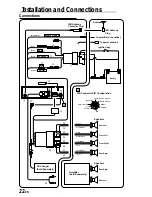
Antenna Receptacle
Connect to the supplied ISO antenna convertor
plug.

2

Remote Turn-On Lead (Blue/White)
Connect this lead to the remote turn-on lead of
your amplifier or signal processor.

3

Power Antenna Lead (Blue)
Connect this lead to the +B terminal of your
power antenna, if applicable.

NOTE

This lead should be used only for controlling the
vehicle's power antenna. Do not use this lead to turn on
an amplifier or a signal processor, etc.

4

Switched Power Lead (Ignition) (Red)
Connect this lead to an open terminal on the
vehicle's fuse box or another unused power
source which provides (+) 12V only when the
ignition is turned on or in the accessory position.

5

Fuse Holder (15A)

6

Battery Lead (Yellow)
Connect this lead to the positive (+) post of the
vehicle's battery.

7

ISO Power Supply Connector

8

Ground Lead (Black)
Connect this lead to a good chassis ground on
the vehicle. Make sure the connection is made to
bare metal and is securely fastened using the
sheet metal screw provided.

9

Remote Control Interface Connector
(TDM-7577R/TDM-7576R only)
To remote control interface box.

!

Rear Output RCA Connectors
RED is right and WHITE is left.

"

DIN Connector
Connect this to the DIN connector on the CD
Changer.

#

DIN Extension Cable

NOTE

Older Alpine CD Changer came with standard, straight
type DIN connectors. In installations where an L-type
connector would simplify installation, the Alpine 4910

02

Adaptor can be used (Sold Separately).

$

Power Supply Connector

%

ISO Connector (Speaker Output)

&

Left Rear (+) Speaker Output Lead (Green)

(

Left Rear (–) Speaker Output Lead (Green/
Black)

)

Left Front (+) Speaker Output Lead (White)

~

Left Front (–) Speaker Output Lead (White/
Black)

+

Right Front (–) Speaker Output Lead (Grey/
Black)

,

Right Front (+) Speaker Output Lead (Grey)

-

Right Rear (–) Speaker Output Lead (Violet/
Black)

.

Right Rear (+) Speaker Output Lead (Violet)

/

RCA Extension Cable (Sold Separately)

To prevent external noise from entering the audio system.
• Locate the unit and route the leads at least 10cm away from the car harness.
• Keep the battery power leads as far away from other leads as possible.
• Connect the ground lead securely to a bare metal spot (remove the coating if necessary) of the car

chassis.

• If you add an optional noise suppressor, connect it as far away from the unit as possible. Your Alpine

dealer carries various Alpine noise suppressors, contact them for further information.

• Your Alpine dealer knows best about noise prevention measures so consult your dealer for further

information.

Содержание TDM-7574R

Страница 1: ...lón 32 01013 Vitoria Alava Apdo 133 Spain Tel 34 45 283588 ALPINE ELECTRONICS OF AUSTRALIA PTY LTD 6 8 Fiveways Boulevarde Keysborough Victoria 3173 Australia Tel 03 9769 0000 ALPINE ELECTRONICS GmbH Kreuzerkamp 7 11 40878 Ratingen Germany Tel 02102 45 50 ALPINE ITALIA S p A Via C Colombo 8 20090 Trezzano Sul Naviglio MI Italy Tel 02 48 47 81 TDM 7577R TDM 7576R TDM 7575R TDM 7574R Designed by ALP...

Страница 2: ...s Más selecciones musicales más versatilidad y más ventajas Un cambiador Alpine de CD añade más opciones musicales a su equipo de sonido Todos los modelos pueden controlarse desde las unidades principales de Alpine y proporcionar un sonido de calidad excepcional El modelo CHA S624 es un cambiador de 6 discos de alto rendimiento con el nuevo DAC M y compatibilidad con Ai NET salida digital óptica m...

Страница 3: ...ews 10 Receiving RDS Regional Local Stations 10 Cassette Player Operation Inserting Ejecting Cassette 11 Normal Play and Pause 11 Dolby B NR Noise Reduction TDM 7577R TDM 7576R only 11 Repeat Play 11 Blank Skip B SKIP 11 Fast Forward and Rewind 12 Scanning Programmes 12 Manual Reverse 12 Programme Sensor P S 12 CD Changer Operation Controlling CD Changer Optional 13 Music Sensor M S Skip 13 Fast F...

Страница 4: ...HE VOLUME EXCESSIVELY Keep the volume at a level where you can still hear outside noises while driving Driving while unable to hear outside noises could be the cause of accident DO NOT USE THIS EQUIPMENT FOR PURPOSES OTHER THAN STATED FOR THE VEHICLE Failure to do so may result in electric shock or injury DO NOT PLACE FOREIGN OBJECTS IN INSERTION SLOTS OR GAPS Do not insert hands fingers or foreig...

Страница 5: ...t must be of the same amperage as shown on the fuse holder If the fuse blows more than once carefully check all electrical connections for shorted circuitry Also have your vehicle s voltage regulator checked Maintenance If you have problems do not attempt to repair the unit yourself Return it to your Alpine dealer or the nearest Alpine Service Station for servicing Installation Location Make sure ...

Страница 6: ... panel make sure that there is no dirt or dust on the connector terminals and no foreign object between the front panel and the main unit Connectable to Remote Control Interface Box TDM 7577R TDM 7576R only You can operate this unit from the vehicle s control unit when an Alpine Remote Control Interface Box optional is connected For details contact your Alpine dealer Initial System Start Up 1 When...

Страница 7: ...yer and FM radio is too great adjust the FM signal level as follows 1 Press and hold the INTLZ button for at least 3 seconds 2 Press the Preset 1 button to select the FM signal level HI High or LO Low to make the signal levels between the FM band and tape player closer Each press toggles between FM LV HI and FM LV LO 3 Press the INTLZ button to cancel the adjusting mode Adjusting Volume Bass Trebl...

Страница 8: ...ady lighting indicating that the station has been memorized The display shows the band preset No with a triangle 9 and station frequency memorized Radio Operation TUNE A ME SOURCE F DN g f UP BAND Manual Tuning 1 Press the SOURCE button until radio frequency appears in the display 2 Press the BAND button repeatedly until the desired radio band is displayed Each press changes the radio bands as fol...

Страница 9: ...the display continues to change while the automatic memory is in process The tuner will automatically seek and store 6 strong stations in the selected band in order of signal strength When the automatic memory has been completed the tuner goes to the station stored in the preset location No 1 NOTE If no stations are stored the tuner will return to the original station you were listening to before ...

Страница 10: ...F2 bands only INTLZ F AF T INFO 3 PTY DN g f UP Setting RDS Reception Mode and Receiving RDS Stations The RDS Radio Data System is a radio information system using the 57 kHz subcarrier of regular FM broadcast The RDS allows you to receive a variety of information such as traffic information station names and to automatically re tune to a stronger transmitter that is broadcasting the same programm...

Страница 11: ...tion mode The T INFO indicator disappears Turning Emergency Alarm On or Off 1 Press and hold the INTLZ button for at least 3 seconds 2 Press the Preset 3 button repeatedly to select the PTY31 ON or PTY31 OFF mode In the PTY31 ON mode the unit will make an emergency announcement when the unit receives the PTY31 Emergency Broadcast signal 3 Press the INTLZ button to activate the selected mode Receiv...

Страница 12: ...e PRIORITY NEWS mode NEWS lights up in the display To disable the PRIORITY NEWS function press the NEWS button NOTE In the PRIORITY NEWS function unlike in the T INFO function the volume does not increase automatically 3 Press the F button to activate the normal mode The function indicator at the top side of the F button will illuminate RDS Operation INTLZ F NEWS 2 Receiving RDS Regional Local Sta...

Страница 13: ... When the end of the tape is reached the unit automatically stops and reverses the tape to play the other side of the tape Cassette Player Operation 2 Press the J button to pause the tape playback The display shows PAUSE Press again to resume the tape playback 3 Press the Eject c button to stop the tape play and eject the cassette The tape direction indicator disappears Dolby B NR Noise Reduction ...

Страница 14: ...hange the tape direction to play the other side of the tape The tape side indicators and change to show which side of the cassette is being played Programme Sensor P S 1 Press the P S DN button once during tape play to return to the beginning of the current selection being played If you wish to return to a selection further back press repeatedly until the number of selections you would like to ski...

Страница 15: ...Changer using the TDM 7577R TDM 7576R TDM 7575R TDM 7574R NOTE The CD controls on the TDM 7577R TDM 7576R TDM 7575R TDM 7574R for the CD operation are functional only when the CD Changer is interconnected with the TDM 7577R TDM 7576R TDM 7575R TDM 7574R 1 Press the SOURCE button to activate the CD Changer The display shows the disc number and track number NOTE To start play or pause play press the...

Страница 16: ...o activate the normal mode The function indicator at the top side of the F button will illuminate SOURCE F TITLE M I X SCAN Disc Scan 1 Press the F button The function indicator at the top side of the F button will turn off 2 Press the SCAN button to play the first 10 seconds of each track on the disc The display shows the disc number SCAN and track number being played during scan play Press to th...

Страница 17: ... 3 Press and hold the TITLE button for at least 3 seconds The first digit blinks 4 Press the DN g or f UP button repeatedly to select the desired letter numeral symbol available for naming 5 Press the TITLE button to store the first character The first character will stop blinking and the display will automatically advance to the next digit When that digit begins to blink you may choose the next l...

Страница 18: ...button 7 8 Button Radio mode Pressing the button will select in ascending order stations programmed into the radio s presets as shown below 1 2 6 CD Changer mode DISC Select UP Button Press the button to select a disc in ascending order 8 g Button Radio mode SEEK DN Button CD mode Press the button to go back to the beginning of the current track 9 f Button Radio mode SEEK UP Button CD mode Press t...

Страница 19: ...s or equivalent 1 Opening the battery cover Slide out the battery cover while firmly pressing outward 2 Replacing the battery Put the batteries in the case observing the polarities as illustrated 3 Closing the cover Push the cover as illustrated until a click is heard e d d e ...

Страница 20: ...on or display Vehicle s ignition is off If connected following instructions the unit will not operate with the vehicle s ignition off Improper power lead connections Check power lead connections Blown fuse Check the fuse on the battery lead of the unit replace with the proper value if necessary Internal micro computer malfunctioned due to interference noise etc Press the Reset button with a ball p...

Страница 21: ... dB Quieting Sensitivity 1 1 µV Alternate Channel Selectivity 80 dB Signal to Noise Ratio 65 dB Stereo Separation 35 dB MW TUNER SECTION Tuning Range 531 1 602 kHz Sensitivity IEC Standard 25 1 µV 28 dB LW TUNER SECTION Tuning Range 153 281 kHz Sensitivity IEC Standard 31 6 µV 30 dB TAPE PLAYER SECTION Tape Speed 1 7 8 ips 4 8 cm sec 0 7 Wow Flutter 0 06 WRMS Signal to Noise Ratio With Dolby B TYP...

Страница 22: ...ure to do so may result in fire or electric shock You must be very careful when connecting wires to the vehicle s electrical system Be sure you do not use leads of factory installed components like an on board computer When connecting TDM 7577R TDM 7576R TDM 7575R TDM 7574R to the fuse box make sure the fuse for the intended circuit of the TDM 7577R TDM 7576R TDM 7575R TDM 7574R has the appropriat...

Страница 23: ...cking pins are fully seated in the down position This can be done by pressing firmly in on the unit while pushing the locking pin down with a small screwdriver This ensures that the unit is properly locked and will not accidentally come out from the dashboard Install the Detachable Front Panel Lock pin Removal 1 Remove the detachable front panel 2 Use a small screwdriver or similar tool to push th...

Страница 24: ...ISO Antenna Converter Plug To amplifier or equalizer ISO Antenna Plug Amplifier Sold Separately CD Changer Sold Separately REMOTE TURN ON BATTERY IGNITION GND Blue White Yellow Green Green Black White White Black Grey Black Grey Violet Black Violet Red POWER ANT Blue Black A A Rch SIG GND Lch Data Ground Data Bus Battery Shield Ground lgnition Power Supply Ground 2 3 4 6 7 9 5 1 8 Ignition Key ...

Страница 25: ...d WHITE is left DIN Connector Connect this to the DIN connector on the CD Changer DIN Extension Cable NOTE Older Alpine CD Changer came with standard straight type DIN connectors In installations where an L type connector would simplify installation the Alpine 491002 Adaptor can be used Sold Separately Power Supply Connector ISO Connector Speaker Output Left Rear Speaker Output Lead Green Left Rea...

Отзывы: