Alpine i509-WRA-JL Скачать руководство пользователя страница 23

Jeep Wrangler

i509-WRA-JL

20220401v1

˜

 23/29

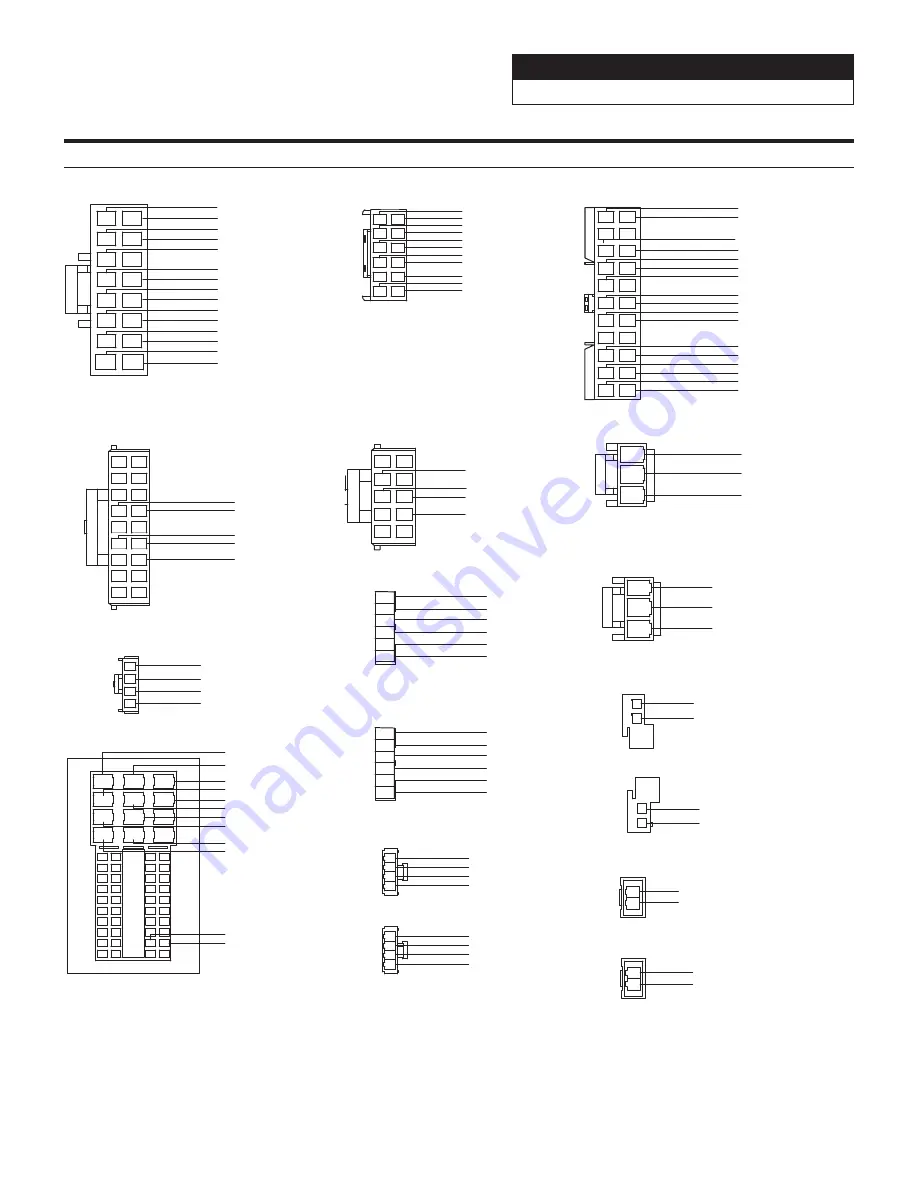
Wire Harness Pin Outs

1

2

3

4

5

6

7

8

9

10

11

12

13

14

15

16

Radio Main

Blue 22AWG
Red 20AWG
Blue/White 22AWG
Orange/White 22AWG
Yellow/Blue 22AWG

Purple 20AWG
Gray 20AWG
Purple/Black 20AWG
Gray/Black 20AWG
Green 20AWG

White 20AWG
Green/Black 20AWG
White/Black 20AWG
Yellow 18AWG
Black 18AWG

1

3

5

7

9

11

2

4

6

8

10

12

Remote Harness

Red/White 22AWG
Brown 22AWG

Aux Power

8
6
4

3
1 2

9 10

7
5

Radio I/O

Orange/White 22AWG

Green/White 22AWG

Yellow/Blue 22AWG

Blue/White 22AWG

1

2

3

Yellow 18AWG

Red 20AWG

Black 18AWG

Maestro Power

Black 18AWG

Green 20AWG

Green/Black 20AWG

Yellow 18AWG

Brown/Yellow 20AWG

Purple/Black 22AWG

Purple 22AWG

1

2

3

4

Wrangler Radio

Purple 20AWG

Purple/Black 20AWG
Green 20AWG

Green/Black 20AWG

Speaker Harness

1

2

3

4

Gray 20AWG

Gray/Black 20AWG
White 20AWG

White/Black 20AWG

Speaker Harness

15 5

4

14
13 3

20

19
18

25
24
23
22

30
29
28
27

26

21

35
34
33

40
39
38
37
36

41

50

52

47

32
31

2

12

1

11

45

42

46

44

43

48

51

49

10

9
8

17 7

6

16

Gray/Black 20AWG

White/Black 20AWG

White 20AWG

Gray 20AWG

Brown/Red 20AWG

1

2

3

Yellow 18AWG

Red 20AWG

Black 18AWG

1

2

Brown/Yellow 22AWG

Brown/Red 22AWG

CAN

1

2

Red/Brown 22AWG

Yellow/Brown 22AWG

CAN Connector

1

2

Red/Brown 22AWG

CAN Connector

Yellow/Brown 22AWG

1

2

Red 20AWG
Black 20AWG

Camera Power

Yellow 22AWG
Black 22AWG

Black 22AWG

Yellow 22AWG

Brown 22AWG

Brown 22AWG

Brown/White 22AWG
Brown 22AWG

Pink 22AWG

Cam Aux Data

Red 22AWG

Purple 22AWG

Black 22AWG

Black 22AWG

Blue 22AWG

Red/White 22AWG
White 22AWG

Purple 22AWG

White 22AWG

White 22AWG

Black 22AWG

Black 22AWG

1

2

3

9

11

13

15

17

4

8

10

12

14

16

18

5

7

6

19 20

21 22

Blue/White 22AWG

Black/White 22AWG
Black/White 22AWG

Blue/White 22AWG

1

2

3

4

5

6

Front Camera

Black 22AWG

Black 22AWG

Red 22AWG
Blue 22AWG
Black 22AWG
White 22AWG

Data SWC

12

11
13 14

16

15
17 18

1 2

4

3

6

5

8

7
9 10

Brown/Red 22AWG

Brown/Yellow 22AWG

Red/Brown 22AWG

Yellow/Brown 22AWG
Yellow/Black 22AWG

4

1

2
3

iDatalink

Blue 22AWG
White 22AWG
Black 22AWG
Red 22AWG

1

2

3

4

5

6

Rear Camera

Black 22AWG

Black 22AWG

Red 22AWG
Blue 22AWG
Black 22AWG
White 22AWG

Green/White 22AWG

Содержание i509-WRA-JL

Страница 1: ...rm to you and others and to protect against damage to property These symbols and their meanings are listed below Make sure you fully understand these symbols before you begin reading the main text Exp...

Страница 2: ...making a hole in the vehicle body be careful to avoid damaging pipes the fuel tank electrical wiring and the like This kind of damage could lead to an accident or fire When installing and grounding th...

Страница 3: ...RA JL 20220401v1 3 29 Tools Required 10mm Socket 8mm Socket 7mm Socket Wire Cutters Extension Ratchet 2 Phillips Screwdriver Torx T20 Torx T47 Panel Removal Tools Wire Fishing Tool Cordless Power Dril...

Страница 4: ...nce Guide Direct Camera Adapter Display Cable Source Unit HDMI Bracket Anti Vibration Foam Screws M5X8LMM x 12 Rear Camera Retention SGS BSV1 WJL V2 0 Camera Module Camera Power Harness Camera Male To...

Страница 5: ...0LMM x 2 Lock Washers x 2 Power Inverter Bracket Display Bracket Tuner Bracket Display Power Key Harness iDatalink Maestro Box Parts ALP MRR ALP HRN WJL3 iDatalink Maestro Module USB HDMI Aux Interfac...

Страница 6: ...is invalid Call ADS at 1 866 427 2999 with the serial number Programming The iDatalink Maestro Module idatalinkmaestro com and follow the installation steps The Maestro module must be programmed speci...

Страница 7: ...ures may be different if you have the 5 0 display The following chart shows which options are available on the different trim levels for the Wrangler JL Retained Features STEERING WHEEL CONTROLS Two F...

Страница 8: ...clips and remove the knee panel under the steering wheel using a panel removal tool 3 The locations of the 6 clips from the previous step 4 Unsnap 10 clips unplug the 2 harnesses and remove HVAC panel...

Страница 9: ...d unit Disconnect and remove the radio 10 Disconnect the harnesses behind the OEM head unit 11 The disconnected harnesses from the previous step These will be used later to connect to the main harness...

Страница 10: ...ck in place 14 For vehicles with heated seats or the power inverter the bracket for the module needs to be removed Remove the 4 10mm screws to remove the bracket Then remove the 2 8mm screws lower and...

Страница 11: ...JL 20220401v1 11 29 19 Unclip 7 clips and remove the center media stack 17 Loosen the clips around the top panel visor area 18 Remove panel above drivers door going to the B pillar Factory Unit Disass...

Страница 12: ...on page 17 3 Mount GPS antenna near driver side B pillar as illustrated on page 17 and run the cable to the knee panel 4 Route radio cables including Radio Main Sirius XM FM and Aux in main harness a...

Страница 13: ...ashers This will mean you will not use two of the M5X8LMM screws from the previous page These two screws are slightly longer and can make it through both brackets 9 Use the factory speed clips from th...

Страница 14: ...odule will look like for the Gladiator JT 14 Use 4 OEM bolts to secure the i509 source unit tuner bracket to the vehicle If the vehicle is equipped with the power inverter it will mount behind the 2nd...

Страница 15: ...t the camera interface module to the violet or red factory camera plug and put it in right side of radio cavity Dip switch 1 will need to be moved down for the Gladiator JT 20 Run chime speaker harnes...

Страница 16: ...bracket to the vehicle using the OEM screws from the OEM radio 25 Apply Anti Vibration Foam to the top of the display Attach the display unit to the display bracket using the 4 M5X8LMM supplied screws...

Страница 17: ...M Camera Module i509 WRA JL Source Unit iDatalink Maestro Module SAT Radio Tuner Sold Separately Harness Route GPS Antenna Installation IMPORTANT Follow the GPS antenna installation procedure shown be...

Страница 18: ...SB CAMERA ANTENNA MAIN REMOTE SXM DISPLAY EX KEY GPS OUT IN Black USB 2 4A Charge Passes Data Gray USB 1 5A Charging Only Front Camera Direct Input Dash Cam Video In Dash Cam Data To Dash Cam See Page...

Страница 19: ...CAMERA BSV INTERFACE LVDS IN USB Flash DIP1 UP Wrangler Down Gladiator DIP 2 3 4 5 6 7 8 All up DIP7 Down Firmware Update VIDEO OUT Power CAN IN Can1 Can2 Rear Camera Violet or Red USB HDMI Rear Camer...

Страница 20: ...REMOTE SXM DISPLAY EX KEY GPS OUT IN Connection Of An External Amplifier There is no way to integrate the factory SiriusXM tuner Once the radio is removed the factory SiriusXM is removed As the title...

Страница 21: ...from the Source Unit a phone would be an example of this HDMI Input iPhone Lightning To HDMI adapter needs to be purchased from Apple Third party adapters may not work USB i509 WRA JL Source Unit To H...

Страница 22: ...White White Black Gray Black Gray Violet Black Violet SUBW FRONT OUT P ANT Blue To power antenna STEERING REMOTE HDMI REMO OUT AUX REMO OUT To steering remote control interface To HDMI Selector Interf...

Страница 23: ...1 11 45 42 46 44 43 48 51 49 10 9 8 17 7 6 16 Gray Black 20AWG White Black 20AWG White 20AWG Gray 20AWG Brown Red 20AWG 1 2 3 Yellow 18AWG Red 20AWG Black 18AWG 1 2 Brown Yellow 22AWG Brown Red 22AWG...

Страница 24: ...er Harness AUX Power 3 pin Black Connector Black Ground Yellow 12V Red Acc 12V Main Harness Yellow Red Black Cut the terminals Solder and heat shrink to AUX Power Connector Remocon Out Remocon In Lin...

Страница 25: ...ne Seek Down Track None Next Preset Preset Folder Preset Folder Voice Voice Or Siri None Off Hook Answer Call None On Hook Hang Up Reject Call None Volume Up Volume None Volume Down Volume Attenuation...

Страница 26: ...5 Select the setting you would like to edit TYPE POWER SOURCE or RECALL LAST STATE 6 TYPE can be set for either LATCHING or MOMENTARY LATCHING means that when the switch is selected it will stay on u...

Страница 27: ...e and that will enable the CAMERA SETTINGS in the Maestro Setup Menu 3 In the Maestro screen select SETUP 4 Select MAESTRO SETUP Note this path in the settings can vary slightly with different Maestro...

Страница 28: ...plug USB power into a 2A source A 2A USB power source must be used to power on the device 2 Android phone is not working with HDMI Using incorrect HDMI adapter If the phone has the feature to use an H...

Страница 29: ...so ensure that no 3rd party interface module s interfere with the Reverse Signal The head unit uses the Reverse Signal to achieve optimal positioning performance 12 iPhone or Android phone is not reco...

Отзывы: