Table of Contents
Important Safety Instructions
Introduction
Package Contents
Front Panel
Rear Panel
Wiring Instructions
FCC Notice
ETL/ETLC Notice
Industry Canada Information
Metallic Loop Test (MLT)
Notes
Wall Mounting Template
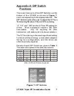
Appendix A: DIP Switch Positions
Appendix B: S/T Bus Configuration
Appendix C: Interface Pin Assignments
Appendix D: Power Source 2 (PS2)
Appendix E: Acronyms
i
1
1
2
2
3
7
13
14
15
15
15
16
17
19
8
12
Figures
Figure 1: UT3620 Perspective View
Figure 2: UT3620 Rear Panel
Figure 3: Interface Wiring Diagram
Figure 4: Power Connector
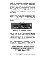
Figure 5: U-Interface Connector
Figure 6: S/T-Interface Connector
Figure 7: DIP Switches
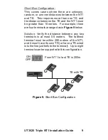
Figure 8: Default S/T Configuration
Figure 9: Short Bus Configuration
Figure 10: Extended Bus Configuration
Figure 11: Y-Bus Configuration
2
2
3
4
4
6
7
8
9
10
11
Tables
Table 1: DIP Switch Position
Assignments
Table 2: S/T-Interface Pin Assignments
Table 3: U-Interface Pin Assignments
Table 4: Power Connector Pin
Assignments
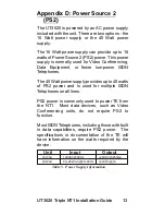
Table 5: Power Supply Information
7
12
12
12
13
Содержание UT3620 Triple NT1
Страница 1: ...UT3620 Triple NT1 Installation Guide ...
Страница 2: ......
Страница 23: ...NOTES 17 UT3620 Triple NT1 Installation Guide ...
Страница 24: ...18 UT3620 NT1 Installation Guide Triple ...
Страница 25: ...Wall Mounting Template 4 73 19 UT3620 Triple NT1 Installation Guide ...
Страница 26: ......
Страница 27: ......

