6
Step 5: Use the wire ties supplied with the
UT3620 and group the U-Interface cables
together followed by the S/T-Interface cables.
Alternatively, group each U-Interface and
corresponding S/T-Interface cables.
When the installation is complete, all LEDs
should stay solid green. Once this is
established, the UT3620 is fully functioning.
Congratulations! You have now
completed installation of your
UT3620 Quad NT1!
If the LED continues to blink slowly, the TE has
not synchronized. Note: Video Conferencing
products often require the software to be
operating to achieve synchronization. Check the
RJ-45 to RJ-45 cable connections, and verify
both RJ-45 ports for the S/T-Interface. Also,
verify the S/T Bus Configuration is correct for the
installation.
If these steps do not help, try moving a known
working S/T-Interface to this port, preferably from
an adjacent S/T-Interface port. If the LED still
does not indicate synchronization, call technical
support.
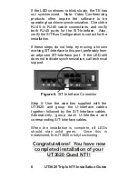
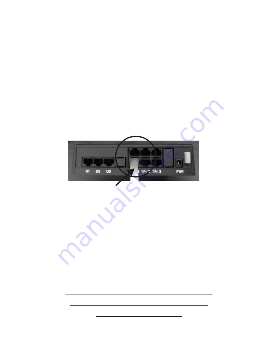
Figure 6.
S/T-Interface Connector
UT3620
NT1 Installation Guide
Triple
Содержание UT3620 Triple NT1
Страница 1: ...UT3620 Triple NT1 Installation Guide ...
Страница 2: ......
Страница 23: ...NOTES 17 UT3620 Triple NT1 Installation Guide ...
Страница 24: ...18 UT3620 NT1 Installation Guide Triple ...
Страница 25: ...Wall Mounting Template 4 73 19 UT3620 Triple NT1 Installation Guide ...
Страница 26: ......
Страница 27: ......

