background image

49

Subject to technical amendments without prior notice  |  83055400iUK – 2.1  |  ait-deutschland GmbH

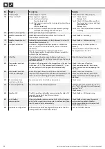
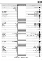
Parameter

Factory setting

Adjustment during 

commissioning *)

Value range (adjustable steps) Access

FlexConfig

OUT 2

ZIP

ZIP • KS • BLP • Enth • – – –  Fitter

OUT 3

ZWE 2

ZWE 2 • FP1 • – – –  Fitter

Silent Mode

Silent Mode

No

Yes • No  Fitter

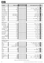
Pump flow

Pump flow lead time 

VBO

1 min

1 – 5 min (

1)  Fitter

Pump flow lead time 

ZUP

60 s

60 – 300 s (

5)   Fitter

Smart

Smart Home ID

1 – 4 (

1)

 User

Heating circuit

No

No • Yes

 User

range +

0 K

0 K – 5 K (

1)

 User

range –

0 K

0 K – 5 K (

1)

 User

mixing circ 1

No

No • Yes

 User

range +

0 K

0 K – 5 K (

1)

 User

range –

0 K

0 K – 5 K (

1)

 User

DHW

No

No • Yes

 User

intelligent defrost

No

No • Yes  Fitter

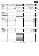
Smart Grid

Decrease Heating

-2 K

-0.5 K – -25 K (

0.5)  Fitter

Increase heating

2 K

0.5 K – 5 K (

0.5)  Fitter

Increase SW

2 K

0.5 K – 10 K (

0.5)  Fitter

Settings parallel connection

IP-Adresses

 User

Master

 User

Slave 1

 User

Slave 2

 User

Slave 3

 User

Switch Cycle

20 min

5 min – 60 min (

1)  Fitter

Parallel Hysteresis

4.0 K

1 K – 10 K (

0.5)  Fitter

Switch Time Cooling

20 min

5 min – 60 min (

1)  Fitter

*) Please enter the adjusted values. Mark not applicable with  —  .

Содержание Luxtronik

Страница 1: ... Heating and Heat Pump Control Controller part 2 Scope of delivery Montage Electrical connections Installation of sensors Dismantling Software update Switching on for the first time Commissioning Program area Cooling Program area Service Appendix ...

Страница 2: ...ned herein is protected by copyright No part of this information may be reproduced transmitted cop ied stored in electronic data systems or translated into another language either wholly or in part without the express written permission of the manufacturer Symbols Information for users Information or instructions for qualified technicians and authorised service personnel DANGER Indicates a direct ...

Страница 3: ...re sensor characteristic curve 44 Overview Defrost cycle Air defrost Flow Max 45 Sensor measuring range 45 SYSTEM SETTING DURING COMMISSIONING 46 ABBREVIATIONS SELECTION 50 PLEASE READ FIRST 2 SYMBOLS 2 SCOPE OF DELIVERY MONTAGE ELECTRICAL CONNECTIONS INSTALLATION OF SENSORS DISMANTLING SCOPE OF DELIVERY 4 Installed control scope of supply 4 Wall control scope of supply 4 MONTAGE 4 Assembly of the...

Страница 4: ...s are installed in the heat pump and are not part of the scope of supply of the heating and heat pump regulator The heating and heat pump regulator is supplied in two variants The variant supplied is dependent on the device type of the heat pump to the controlled INSTALLED CONTROL SCOPE OF SUPPLY In the case of devices for internal mounting the motherboard of the heating and heat pump regulator is...

Страница 5: ...ion for circulation pump PWM control signal 2 Loosen fastening screw of the folding bracket for the cable entry and pull the folding bracket downwards until it is possi ble to fold away upwards Fold folding bracket upwards and away to the side 3 Remove covers from the cable ducts NOTE The wall mounting material included in the scope of sup ply requires solid masonry IMPORTANT Ensure that the screw...

Страница 6: ...s including the TRL return sensor on the return to the heat pump 4 Connect the BUS communication cable which leads to the heat pump to terminal block X10 of the controller board Then route the BUS communication cable downwards and through the cable ducts and through the cable entry to the outside 5 Connect the 230 V voltage supply line to the voltage supply terminal block NOTE The terminal block h...

Страница 7: ...erminal block Analog inputs X12 Terminal block Analog outputs X13 Terminal block LIN Bus interface for control unit X14 Terminal block Modbus interface 4 BUS communication cable to the outdoor unit 5 other 230 V outputs circulation pumps mixers 6 PWM control signal for circulation pump 7 230 V power supply to the outdoor unit K Cable ducts CONTROL UNIT VARIANTS Depending on the heat pump type one ...

Страница 8: ...he screen of the control unit reports an error IMPORTANT Mount the external sensor on the north or northeast side of buildings The sensor must not be exposed to direct sunlight The cable gland must point to the base 1 Open the housing of the external sensor and align 2 m over the base of the fastening point 1 Quick release screws 2 NTC sensor element 2 2 kΩ at 25 C 3 Cable clamps 4 Housing sealing...

Страница 9: ... the on screen instructions IMPORTANT Only install updates downgrades that are cited as valid updates Gültiges Updates in the screen list Switching on Commissioning When switching on the controller voltage or after a restart of the heating and heat pump controller reset a self test is carried out to check whether the basic components of the heat pump system are available The components displayed v...

Страница 10: ...OTE If no heat source is selected and the enquiry is only an swered by navigating to and selecting Brine is auto matically set as the heat source A subsequent change of the heat source medium as well as T HS min is only possible with customer service access If this screen is then displayed disconnect the heating and heat pump con troller from the power supply check the 3 pole cable for the BUS con...

Страница 11: ...ore information on the commissioning assistant please re fer to the corresponding sections in this operating manual NOTE As soon as the startup guide has been executed once the menu item Reset Startup Parameters appears on the dis play instead of the Startup guide menu item FIX STARTUP PARAMETERS With installer or customer service access it is possible to save the settings made during commissionin...

Страница 12: ... the system components required for the emergency mode were detected during the self test The emergency mode is activated automatically A connection error is first displayed on the screen of the heating and heat pump controller Im Bildschirm des Heizungs und Wärmepumpenreglers wird zu nächst ein Kommunikationsfehler ausgegeben Example of a connection error displayed on the screen Beispiel eines im...

Страница 13: ...bridge if cooling is provided via the flow cooler NOTE The minimum flow temperature of cooling is factory set to 18 C This value can be changed in the menu Determin ing temperatures in the menu item min flow cooling IMPORTANT For brine water heat pumps with integrated hydraulic components do not set the minimum flow temperature of cooling to 18 C page 22 Determining temperatures If the cooling fun...

Страница 14: ...themenufield OTdiff MC1 appearshere Thenenteracorresponding temperaturespreadinKelvin hysteresis CC Hysteresis cooling regulator Without an expansion board installed displayed only for reversible air water heat pumps and controls the auto matic changeover from passive to active cooling A B K K D C A There will be a request for active cooling in this tem perature range B There will be no request fo...

Страница 15: ...ed on the outdoor temperature The calculation is based on the value entered in Kelvin under OT diff MC1 but is restricted to a spread of 1 K 10 K adjustable in 0 5 steps A Temperature B Time 1 Outdoor temperature 2 Set temperature mixing circiut 3 set AT outdoor temperature difference ENABLE ACTIVE COOLING NOTE The active cooling function can only be used if the system is utilised in accordance wi...

Страница 16: ...tion temperature EVI EVi Superheat Superheating temperature EVI Target EVI superheat Superheating target temperature EVI Condensation temp Condensation temperature Liquid temp before EEV Temperature of the liquid refrigerant upstream of the electronic expansion valve heating evaporating temp Evaporation temperature condensing temp Condensation temperature TFL1 Temperature of the liquid refrigerant...

Страница 17: ...ic expansion valve cooling VBO set value Setpoint brine circulation pump VBO current Current value brine circulation pump heat sys pump set value Setpoint heating circulating pump heat sys pump current Current value heating circulating pump suppl pump set value Setpoint additional circulating pump suppl pump current Current value additional circulating pump Query inputs The menu is not shown in fu...

Страница 18: ...1 since Additional heat generator 1 running since 2 hg since Additional heat generator 2 running since Switch on delay Net input delay Swi c time Off time switching cycle read CPd Compressor Read CPd HC Add time Heating control more time HC Less time Heating time less time ThDsin sin Thermal disinfection running since block ser wat Off time domestic hot water Freig ZWE HZ Duration of the release o...

Страница 19: ...ecial con figuration of the heating and heat pump controller with additional software that is subject to a charge Operating manual Connection to a building services man agement system via BACnet IP ModBus TCP NOTE Maximum the last five disconnections are displayed If an entry is clicked the corresponding information for this entry is displayed Query the facility status The menu is not shown in ful...

Страница 20: ... stat page 33 Smart The menu is not shown in full here set temperature HC Setpoint temperature heating circuit set temperature MC1 Setpoint temperature mixing circuit 1 Targ service water Set point temperature domestic hot water preparation target value max Highest requirement setpoint from the Smart system UFH total HC Number of floor heating circuits assigned to the heating circuit UFH open HC N...

Страница 21: ... the installer password 9445 may only be carried out by qualified technicians and must be blocked for unauthorised persons After service work it is essential to reset the data access to User enter and save number code 0000 NOTE The manufacturer is not liable for damage resulting from wrong program settings not oriented towards the system components If the rotary pushbutton has not been used for 3 ...

Страница 22: ... for the release temperature for the air defrost Below the set temperature the air defrosting is locked IMPORTANT Set air defrost only if device type is approved for air de frost TVth disinf2 TDI setpoint temperature Setting for the setpoint temperature for the thermal disinfection in the domestic hot water preparation Flow 2 CP SW Flow 2nd compressor Domestic hot water Setting for the flow temper...

Страница 23: ...time the displayed value is the minimum limit value for settable cooling setpoint temperatures Scroll all the way down cancel or save the settings T HS min Minimum heat source temperature Setting for the minimum permissible temperature at the heat source outflow of the heat pump for S W devices With AS access a value above 9 C can be set necessary for integration with intermediate exchangers for W...

Страница 24: ...el tank multifunction tank NOTE External return flow sensor TRLext required for Sep tank setting Hot gas utilisation desuperheater only LWP Higher temperatures of up to 75 C are available with hot gas utili sation The temperature is not always guaranteed The heat pump must already be in operation due to another requirement The heat pump will switch off with a desuperheater temperature of 80 C The ...

Страница 25: ...If the heating limit is exceeded the heating circulation pump switches off SW HP max Maximum running time domestic hot water preparation Heat pump After the set time has expired the 2nd heat generator in the domestic hot water preparation energises but only if this has been released previously in the heating mode Defr cycle max Defrost cycle time maximum time between two defrost processes You can ...

Страница 26: ...ntrols according to the setpoint temperature in the screed heating program wo mixer If the mixer is defined as a discharge mixer it always starts up during the screed heating program Defrost Air Air defrost No Air defrost not released Yes Air defrost generally released above the set temperature Approved appliances see page 45 Overview Defrost cy cle Air defrost Flow Max IMPORTANT Do not set an air...

Страница 27: ... page 30 Additional heat generator El Anode Electrical anode Impressed current anode in the domestic hot water tank Yes Impressed current anode present No Impressed current anode not present IMPORTANT In the case of devices with an impressed current anode tank Yes must be set in this menu field in order to ensure the corrosion protection of the tank The impressed current anode must be connected ac...

Страница 28: ... function deactivated in the factory Yes Activated the required hot water value becomes the hot water target value Part 1 of the controller manual program area Domestic Hot Water section Hot water reheating aux serv water max maximum time period for hot water reheating maximum time period during which the hot water should be reheated If this time period is exceeded the hot water reheating is cance...

Страница 29: ...imum power of the heating circulation pump limitation for flow noise can be manually adjusted Output heat max Maximum performance of heating circulation pump only with control heating auto visible and adjustable Control dhw Control of the domestic hot water charging pump Auto Automatic control Manual Additional menu entry visible output dhw Performance of the DHW charging pump manually adjustable ...

Страница 30: ...ng element not released during the El sup blockade Function No without function Heating Heating SW Service water Domestic hot water If activated no ZWE 1 used for domestic hot water heating Position Tank Integrated directly in or on the heating or hot water storage tank no ZWE 2 connected Outlet The corresponding output contact for electrical connection of the ZWE is displayed automatically If a t...

Страница 31: ...ings are saved These must be strictly ad hered to Inverter The Inverter function makes it possible to control the operating frequency of the compressor and thus the output frequ limit start Lower limit of the operating frequency rotational speed of the compressor frequency limit stop Upper limit of the operating frequency rotational speed of the compressor Freq SW Frequency specification for domes...

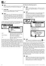
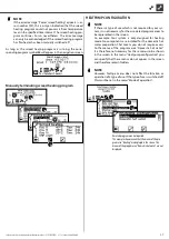
Страница 32: ...on the menu field Timers for pro gramming the operating times appears after the menu has been exited and then called up again The Silent Mode operating times are programmed as described in the section Setting the time programs of the heating circle Part 1 of the controller maunual program area Info and Quick Setting section Setting the time programs of the heating circle During the set times the h...

Страница 33: ... heat pump operates in the setpoint value range plus increase heating HR heating hysteresis in heating mode NOTE Higher increases in temperatures can lead to loss of comfort in Smart Grid operation The return flow limitation temperature must be inspected with integration of a storage tank in series Domestic hot water preparation The heat pump sets a new setpoint value for the hot water which is th...

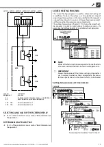
Страница 34: ...grams Smart Grid a X4 X5 SG1 SG2 Legende Betriebsmittel A1 A3 SG1 SG2 IN5 IN6 1 2 3 1 2 A B C D E F 3 AIT ait deutschland G ÄM999 2019 08 10 2019 AP L1 L1 L1 L 2 2 IN1 IN2 IN3 A1 A2 A1 A2 IN4 IN5 IN6 IN7 A3 A1 Änderung Datum Datum Bearbeiter Geprüft Norm Name 09 10 2015 Pfleger R Klemmenplan SG R a X4 X5 SG1 SG2 Legend Equipement A1 A3 SG1 SG2 IN5 IN6 UK Function Controller board Attention I max 6...

Страница 35: ...ed Setting temperatures and time intervals Example Procedure repeat for the table lines Flow2 to Flow10 Klemmenplan SG Ready HZ I O SG1 SG2 Legend Equipement A1 A3 SG1 SG2 IN3 IN4 UK Function Controller board Attention I max 6 3A 230VAC Sub distribution unit internal installation Smart Grid activation 1 Smart Grid activation 2 831210 3 4 5 6 7 8 8 A B C D E F Blatt Bl 1 1 3 4 5 6 7 AIT 831210 Klem...

Страница 36: ...mix er must be set under the Screed heating system setting Starting screed heating program NOTE While the screed heating program is running 10 C is dis played as the outdoor temperature It is not possible to heat water NOTE In the screed heating program all connected heat generators are released if necessary However the following applies A heating system is designed for heating in general and not ...

Страница 37: ...ng a menu does not affect the function or operation of a type of use If the type of use is switched off this must be set in the menu Mode of operation Deselect program area not required The example shown reveals that the menus of the pro gram area Heating are displayed in the screen The menus of the program area Domestic hot water are not displayed NOTE If the error message Power screed heating ap...

Страница 38: ...r manual program area Service sec tion Data logger CONTROL PANEL Adjusting the contrast of the control unit display Part 1 of the controller manual program area Service sec tion Basic Information on the operation Web server Part 1 of the controller manual program area Service sec tion Control Panel Web server Remote maintenance Part 1 of the controller manual program area Service sec tion Control ...

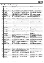
Страница 39: ...ug and connection line 712 Domestic hot water sensor Please call fitter Break or short circuit in the domestic hot water sensor No fault shutdown Check domestic hot water sensor plug and connection line 713 HS on sensor Please call fitter Break or short circuit in the heat source sensor inlet Check heat source sensor plug and connection line 714 Hot gas SW Reset in hh mm Check thermal application ...

Страница 40: ... circuit in the sensor External energy source Check sensor External energy source plug and connection line 736 Error solar collector Please call fitter Only possible with installed expansion board Break or short circuit in the solar collector sensor Check solar tank sensor plug and connection line 737 Error solar tank Please call fitter Only possible with installed expansion board Break or short c...

Страница 41: ...nsor is defective Check the sensor connector and connection cable 780 EVI sensor EVI sensor is defective Check the sensor connector and connection cable 781 Liquid temp sensor before EXV Liquid temperature sensor upstream of the ex valve is defective Check the sensor connector and connection cable 782 Suction gas EVI temp sensor Suction gas EVI temperature sensor is defective Check the sensor conn...

Страница 42: ... connection has no internet connection to the remote maintenance server Establish internet connection 802 Temperature electrical switch box Shutdown will be triggered when temperature in the electrical switch box 80 C If the temperature falls below 70 C then the heat pump will start up again Reset automatically Check fan for correct function Check connection cable Check sensor Check electrical con...

Страница 43: ...43 Subject to technical amendments without prior notice 83055400iUK 2 1 ait deutschland GmbH ...

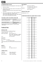
Страница 44: ...a INSTALLATION Only in frost free dry and weatherproof rooms Ambient temperature 0 C 35 C Electrical connection 230 V AC 18 VA 0 1 A max power consumption regulator without any appliances connected Fuse 1 6 A transformer OUTPUTS Relay contacts 8 A 230 V Fuse 6 3 A for all relay outputs In total consumers up to 1 450 VA can be connected to the out puts INPUTS Optocoupler 230 V Sensor inputs NTC sen...

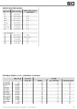
Страница 45: ...140 C 150 C TSK 20 C to 140 C 150 C or 5 C TB2 0 C to 100 C 75 C TB3 0 C to 100 C 75 C TEE 0 C to 100 C 5 C OVERVIEW DEFROST CYCLE AIR DEFROST FLOW MAX Defrost cycle Air defrost Flow Max from end flow Max min AT flow max low limit of applic LW 160H A V 45 65 15 60 LW 161H A V variable 65 15 60 Paros 4 variable 65 2 45 LWV 82R1 3 variable 60 5 45 LWV 122R3 variable 60 5 45 LWAV 82R1 3 variable 60 5...

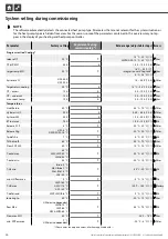
Страница 46: ... h 0 h 12 h 0 5 User OT undercut 12 h h 0 h 12 h 0 5 User max room temp 12 h h 0 h 12 h 0 5 User Temperatures Limit Return 50 C C 35 C 70 C 1 Fitter Hysteresis HC 2 0 K K 0 5 K 6 0 K 0 5 Fitter hysteres SW 2 0 K K 1 0 K 30 0 K 1 Fitter RT incr max 7 0 K K 1 0 K 10 0 K 1 AS Release 2 CP 5 C C 20 C 30 C 1 Fitter Release 2hg L W 2 C S W W W 16 C C 20 C 20 C 1 Fitter Tp defr Air 7 C C 6 C 20 C 1 AS TV...

Страница 47: ...at cool Fitter Error no 2hg no 2hg Heating DHW with 2hg Fitter Service water 1 sensor sensor Thermal User Service water 2 CP CP h wCP Fitter Service water 3 with CP wo CP with CP Fitter Service water 4 set value set value Max Factory Service water 5 device dependent wo HSP with HSP par HUP Fitter SW HP max 0 h 0 h 8 h 0 5 User Defr cycle max 45 min 45 60 75 90 120 180 240 min Fitter Defrost Air No...

Страница 48: ...to Manual Fitter output heat nom 100 1 100 1 Fitter output heat Min 100 1 100 1 Fitter Output heat max 100 50 100 1 Fitter Control dhw Auto Auto Manual Fitter output dhw 100 1 100 1 Fitter output dhw max 100 50 100 1 Fitter output cooling 100 1 100 1 Fitter control VBO Auto Auto Manual Fitter output VBO 100 1 100 1 Fitter output VBO cooling 100 1 100 1 Fitter dT cooling 5 K 1 K 5 K 0 1 Fitter Set ...

Страница 49: ...ating circuit No No Yes User range 0 K 0 K 5 K 1 User range 0 K 0 K 5 K 1 User mixing circ 1 No No Yes User range 0 K 0 K 5 K 1 User range 0 K 0 K 5 K 1 User DHW No No Yes User intelligent defrost No No Yes Fitter Smart Grid Decrease Heating 2 K 0 5 K 25 K 0 5 Fitter Increase heating 2 K 0 5 K 5 K 0 5 Fitter Increase SW 2 K 0 5 K 10 K 0 5 Fitter Settings parallel connection IP Adresses User Master...

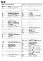
Страница 50: ...ter heat pump outdoor LWC Air Water Compact heat pump LWCV Performance controlled Air Water Compact heat pump LWD Air Water heat pump Dual Abbreviation Meaning LWDV Performance controlled Air Water heat pump Dual LWI Air Water heat pump indoor LWP Air Water heat pump serie professional LWV Performance controlled Air Water heat pump indoor MA Mixer open MC Mixing circuit MK Mixing circuit MSW Brine...

Страница 51: ...rcuit UWP Circulation pump VBO Fan well or brine circulation pump VD Compressor W W Water water heat pump WP Heat pump WW Domestic hot water WWC Water water Compact heat pump WWT Domestic hot water thermostat WZS Bine Water heatstation WZSV Performance controlled Bine Water heatstation ZIP Circulation pump ZUP Additional circulation pump ZWE Second additional heat generator NOTE Abbreviations that...

Страница 52: ...ait deutschland GmbH Industriestraße 3 D 95359 Kasendorf E info alpha innotec de W www alpha innotec de alpha innotec an ait deutschland GmbH brand UK ...

Отзывы: