SBP SERIES USER MANUAL
AC-COUPLED BATTERY
STORAGE RETROFIT
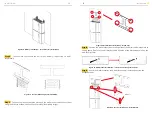
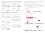
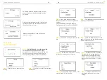
Step19
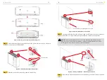
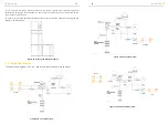
Connect the power cable of the top battery from Step 4 to the terminals of the
cable box. Make sure that red connects to red and black connects to black.
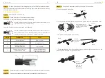
Step20
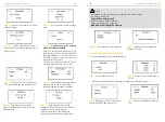
Close the battery covers and connect the PV-MC4 connectors to the system
(connection on both sides). Also, connect all AC cables, the meter communications cable
METER, and the Ethernet cable LAN. Then close the cable box cover.
The installation is now complete.
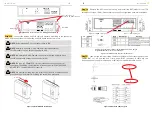
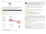
Step21
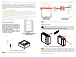
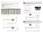
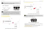
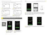
Open the front cover of the last battery and remove the DIP cover. Now set the
DIP switch 2 to "on" mode and close the cover again.
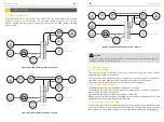
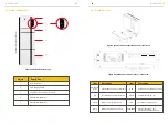
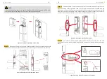
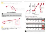
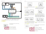
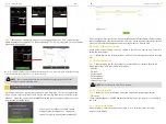
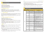
Figure 31 Earthing Point of Battery
& INV
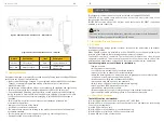
Figure 32 PV Wiring
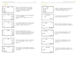
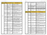
1. If there is
only one BAT
, the DIP switch of this BAT must be set following:
2. If there are
two or more than two
BATs, the DIP switch of the BATs must be set following:
Battery
Position
DIP 1
Battery
OFF
ON
OFF
OFF
DIP 2
DIP 3
DIP 4
DIP Switch
Battery
Position
DIP 1
Non-bottom
battery
Bottom
battery
OFF
OFF
ON
OFF
OFF
OFF
OFF
OFF
DIP 2
DIP 3
DIP 4
DIP Switch
INSTALLATION
INSTALLATION
NOTE:
In Australia and New Zealand, please find the earthing point on the right side of the
battery and connect the earthing point of all of the batteries
and INV
to the ground
refer to AS 3000.
NOTE
: The DIP setting is only changed on the last battery.
Earthing Point
4*MC4
Figure 33 DIP Operation
23
24


