background image

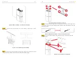
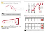
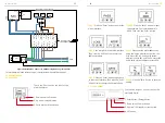
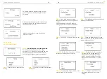
Figure 26 Network Cable Type B

Figure 23

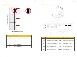
 CB front and back view

, Wiring Connectors

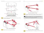
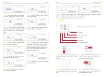
Figure 24 WiFi Module installation

Step13-5 

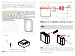
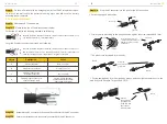
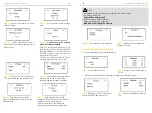
   Connect the Backup and Grid cables in advance according to the connector 

mode, and connect them to the Backup and Grid board connectors in turn.

Step14 

   Remove the WiFi panel on the top and install the WiFi module (tool: T20 

screwdriver, torque: 1.6Nm). Please refer to section 5 configuration network instructions. 

Step15 

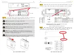
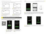
    Take out the communication cable set provided in the accessory parts of one 

SMILE5-BAT,  cut  off  one  end  and  crimp  a  new  RJ45  connector.  If  there  are  two 

batteries, you only need to remake one of battery communication cable on site.

INSTALLATION 

INSTALLATION 

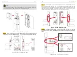
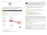
NOTE

: Recommended AC circuit breaker rating is 32A.

NOTE

: Installer in Australia or New Zealand 

could 

install external 

circuit breaker or switch for backup and grid side.

NOTE

: In Australia and New Zealand, the neutral of backup and grid circuit 

should be externally connected on the neutral bar. 

NOTE

:  No external earthing required. After the PE line of AC cables has been 

grounded, the whole inverter including the case will be grounded.

NOTE

: The type AC 


30mA 

RCD 

could 

be installed on the backup port of 

the system. In addition, the installation of inverter must fulfill AS/NZS 3000, 

AS/NZS 4777.1 and AS/NZS 5033

 standards

.

WiFi Panel

19

20

Bat Cable

Bat Cable

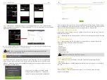
PV connection port

Connect with MC4 connector

DRMs for DRED connection

BAT for Communication

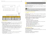
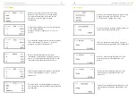
Figure 25 Communication interface of the inverter

PS: This series inverter use RJ45 socket as DRM connection, the pin 

assignment table has been shown on the left

Содержание SMILE5 AU

Страница 1: ...ia Pty Ltd 61 402 500 520 Sales 61 1300 968 933 Technical Support australia alpha ess com www alpha ess com au Suite 1 Level 1 530 Botany Road Alexandria NSW 2015 Alpha ESS Italy S r l 39 599 239 50 info alpha ess it www alpha ess it Via Loda 17 41013 Castelfranco Emilia MO Alpha ESS Korea Co Ltd 82 64 721 2004 korea alpha ess com 2F 19 4 Nohyeong 11 gil Jeju si Jeju do Republic of Korea Alpha ESS...

Страница 2: ...perate the system before reading through the manual Copyright Statement Version Information Date Version Content Notes are added for better overview purposes RJ45 connecting diagram was updated Package parts list modified Power definition modified ADL3000 3 phase connection added Differentiation of outdoor and indoor versions Figures changed after firmware version update Figures and installation s...

Страница 3: ... system The operators should be familiar with the Product Instruction While maintaining the maintainer is not allowed to operate any equipment until all the equipment has been turned off and fully discharged 1 2 3 Protection of Warning Sign The warning signs contain important information for the system to operate safely and it is strictly prohibited to torn or damage them Ensure that the warning s...

Страница 4: ...matched specification to prevent electric arcs or shocks 1 2 6 Moisture Protection It is very likely that moisture may cause damages to the system Repair or maintaining activities in wet weather should be avoided or limited 1 2 7 Operation After Power Failure The battery system is part of the energy storage system and stores life threatening high voltage even when the DC side is switched off Touch...

Страница 5: ...dity Do not mount the inverter and the battery pack in areas containing highly flammable materials or gases If moisture has penetrated the system e g due to a damaged enclosure do not install or operate the system Do not move the system when it is already connected with battery modules Secure the system to prevent tipping with restraining straps in your vehicle The transportation of AlphaESS SMILE...

Страница 6: ... connected to Inverter SMILE5 BAT Battery 1 SMILE5 BAT Battery 2 External Device Control Interface Inverter Debug Communication Meter Communication Port Battery Communication Port USB Debug Communication Port Power Dispatching Port Net Wire Connection Port External Expansion Port Or External Dispatching Port Description Object Item Item Description Description Dry Contact Relay INV Meter BMS USB D...

Страница 7: ...Cable Box Part without Covers left View 2 1 Installation Site and Environment 2 1 1 General This SMILE5 energy storage system is outdoor version and can be installed in an outdoor or an indoor location When SMILE5 systems are installed in a room SMILE5 must not be hampered by the structure of the building the furnishings and equipment of the room The SMILE5 is naturally ventilated The location sho...

Страница 8: ...E5 and the ceiling or any object above the system is less than 900 mm the ceiling or structural surface a b o v e t h e s y s t e m m u s t b e m a d e o f noncombustible material within a radius of 600 mm around the system The SMILE5 must be mounted to ensure the highest point is not more than 2 2 m above the ground or the platform Figure 9 Limit Distance of Installation to Neighboring Objects Fi...

Страница 9: ...e a Φ8mm drill to drill holes at a depth of about 70mm in the wall for subsequent fixation of the mounting plates Step 7 Remove the debris baffle and secure the battery to the wall with screws and gaskets Step 5 Assemble the battery mounting panel on the battery INSTALLATION INSTALLATION M5 10 Screws Debris Baffle drill φ8 depth about 70 mm φ8 60 M6 Gasket NOTE Place a cover paper foil etc over th...

Страница 10: ...e wall bracket the mounting plate of the battery and mark points as shown above Remove the wall bracket and drill holes at the marked position on the wall Drill φ12mm Step 9 Take out the inverter position plate and the wall bracket and connect them using the M4 nuts as shown above Check carefully if everything is tight Figure 18 Battery Installation Second Battery Installation INSTALLATION INSTALL...

Страница 11: ... for the AC connection For grid AC cables the stripping method is as following Strip the insulation sheath of the three core AC cable for about 30mm Strip L N and PE cables for 6 7mm respectively Strip the insulation sheath of the three core AC cable for about 35mm Cut L and N cable for 5mm Strip L N and PE cables 6 7mm for respectively to make sure X length is 5mm longer than Y length of L N cabl...

Страница 12: ... Recommended AC circuit breaker rating is 32A NOTE Installer in Australia or New Zealand could install external circuit breaker or switch for backup and grid side NOTE In Australia and New Zealand the neutral of backup and grid circuit should be externally connected on the neutral bar NOTE No external earthing required After the PE line of AC cables has been grounded the whole inverter including t...

Страница 13: ... all covers if you want to connect further battery modules you must mount them before closing Step18 Connect the power cables of the bottom battery from Step 4 to the side terminals of the top battery Make sure that red connects to red and black connects to black Step16 Hang the inverter onto the wall bracket adjust the entire system and ensure that the battery and the inverter have been securely ...

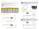
Страница 14: ...o on mode and close the cover again Figure 31 Earthing Point of Battery INV Figure 32 PV Wiring 1 If there is only one BAT the DIP switch of this BAT must be set following 2 If there are two or more than two BATs the DIP switch of the BATs must be set following Battery Position DIP 1 Battery OFF ON OFF OFF DIP 2 DIP 3 DIP 4 DIP Switch Battery Position DIP 1 Non bottom battery Bottom battery OFF OF...

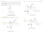
Страница 15: ...em You can connect up to 6 batteries 2 each mounted on top of each other to the SMILE 5 To do this carry out the individual installation steps as for the first two batteries including the DIP setting on the last module Figure 35 DC coupled system INSTALLATION INSTALLATION 2 2 3 Single Line Diagram Figure 37 Hybrid coupled system Figure 34 Increase the Battery Modules Figure 36 AC coupled system 25...

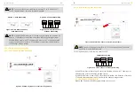
Страница 16: ...plug Table 1 CT meter ratio and accuracy table For AC Hybrid system there are two meter needed ADL 3000 single phase connection without CT without meter plug if applicable ADL 3000 single phase connection without CT with meter plug if applicable Figure 42 ADL 3000 single phase Connect with CT without Meter Plug Option 1 with Meter Plug Figure 40 Two Meter Connect with Meter Plug Figure 41 Two Mete...

Страница 17: ...eter plug Figure 48 ADL 3000 three phase Connect with CT without Meter plug ADL 3000 three phase connection without CT with meter plug if applicable ADL 3000 three phase connection without CT with meter plug if applicable ADL 3000 three phase connection with CT without meter plug if applicable Figure 49 ADL 3000 three phase Connect with CT with Meter plug INSTALLATION INSTALLATION NOTE Connect the...

Страница 18: ... Meter2 If the ACR10 meter is used as a grid meter the direction of arrow in CT should point away from the grid to the energy storage system If the ACR10R meter is used as a PV meter in hybrid system the direction of arrow in CT should point away from the PV inverter to the energy storage system Backup Box Connect to SMILE5 single phase grid in house NOTE To connect the current transformer connect...

Страница 19: ...to input the password The initial password is 0000 Then click the Enter button 2 3 5 2 ADL3000 2 3 5 1 SM60A 2 3 5 Meter setting There are 3 buttons on the front of the electricity meter 1 Down arrow shift button 2 Up arrow value adjustion 3 Enter button Menu button There are 4 buttons on the front of the electricity meter 1 Enter button Energy button 2 Down arrow Power button 3 Up arrow Voltage c...

Страница 20: ...ing is completed Step 8 Click the SET button to enter the following interface Step 9 Click the SET button again to enter the save interface Step 10 Click the Enter button to enter the following interface press the up and down arrow keys and set no to YES to save the configuration Step 11 Click the Enter button and the setting ends 2 3 5 3 ACR10R There are 5 buttons on the meter s front 1 Enter key...

Страница 21: ... backup load is applied 1 2 Step 4 Open the outer shell of the cable box Open the battery switch cover and turn on the battery switch on the cable box Step 5 Press power button on all the batteries until the indicator lights turn on Step 6 Close the battery switch cover and the outer shell of the cable box 3 2 Switch Off Step 1 Press the power button on all the batteries till the lights turn off S...

Страница 22: ...s not from a battery normal ABC fire extinguishers can be used for extinguishing Fire fighting instructions 1 If fire occurs when charging batteries if it is safe to do so disconnect the battery pack circuit breaker to shut off the power to charge 2 If the battery pack is not on fire yet extinguish the fire before the battery pack catches fire 3 If the battery pack is on fire do not try to extingu...

Страница 23: ...day s or total electricity quantity generated from the PV panels Grid Charge interface displays today s or total electricity quantity battery charged from the grid Grid interface displays the real time information on the ultility grid side voltage U current I frequency F PInv PMeterAC PMeterDC Solar interface displays the real time information of PV side voltage U1 current I1 power P1 voltage U2 c...

Страница 24: ...rk mode self use or force time charge Step 4 Set on grid capacity storage capacity and number of PV strings MPPT number On grid capacity Existing PV capacity Storage capacity PV capacity on SMILE5 Step 5 Click the Battery Function and check battery type SMILE5 BAT Step 6 Check SOC Calibration function set No Step 7 Check the Battery Ready function set No If you only use the inverter without batter...

Страница 25: ...ick Date Time and set up the date and time Step 19 Click Ethernet to set the IP address DHCP mode means that setup IP address is set up automatically If you want to set up the IP address manually please choose manual mode Step 1 Click Enable to set yes Step 2 Set the priority of the load L1 L2 L3 Step 1 Please go to the function menu choose ModBus and press enter Step 2 Please set Modbus enable as...

Страница 26: ...uccessful click Next Step 5 please repeat Step 1 to 4 to set the other device as L2 slave L3 slave Step 4 Please choose Mode as Parallel mode and press enter CONFIGURATION NETWORK WIFI OPTIONAL CONFIGURATION NETWORK WIFI OPTIONAL Register Login Please make sure that the POWER light of the Wi Fi module is always on and then connect the mobile phone Wi Fi to the Wi Fi Network named after the S N num...

Страница 27: ...r CT PV Meter Safety Regulations kW CT Meter Meter Connect to the hotspot Router Configuration System Configuration OK Runnig information System information S N AL4001019000000 Model Storion Senergy Safety Regulations AS4777 Battery Installed Capacity kWh 0 0 On Grid PV Capacity kW 5 8 Meter 0 Inverter Version V00 00 EMS Version V1 03 25 BMS Version V0 00 System information Connect to the hotspot ...

Страница 28: ... update the inverter firmware If the problem has not been solved please contact AlphaESS service center Please turn off the parallel connection mode and check if the configuration is correct Please turn off the parallel connection mode and check if the configuration is correct and the communication cables are normal Every six months to one year Check if the cable connections are loose Check whethe...

Страница 29: ...irmware versions to the same Check whether the wiring and check whether inverter load exceed the maximum discharge power of the battery Please restart the battery system If there is still a problem please contact the service center Please check if the communication cable between the slave battery and BMS is not connected or restart the battery Please confirm that the ambient temperature is higher ...

Страница 30: ... not been solved please contact AlphaESS service center Please update the inverter firmware If the problem has not been solved please contact AlphaESS service center Please update the inverter firmware If the problem has not been solved please contact AlphaESS service center Check if the wirings between inverter and grid and backup are correct Please check whether the critical loads of the inverte...

Страница 31: ...LE5 INV 2 x 12 A Max PV Input Power 2 x 3300 W 580 V 2 125 550 V 2 x 15 A Phase Backup Display Communication Start Up DC Voltage Humidity Single Phase When the temperature is below 0 C or above 40 C the performance will be limited 2 needs to install expansion pack Under specific test conditions 6 SMILE5 BAT 5 7 kWh 51 2 V 56 A 0 5C 10 000 6 6 SMILE BAT 10 3P 10 3 kWh 51 2 V SMILE BAT 13 3P 13 3 kW...

Отзывы: