background image


13 

ALLTRONIC GmbH, Raiffeisenstraße 11, 89438 Holzheim   


Service-H49 9075 95 88 3-28   


3. Operations 

3-1. Button operation 

Button 

Function   

ON/Mute 

Button   


Turn on the UPS:

 Press and hold ON/Mute button for at least 2 seconds 

to turn on the UPS. 


Mute the alarm:

 After the UPS is turned on in battery mode, press and 

hold this button for at least 3 seconds to disable or enable the alarm 

system. But it’s not applied to the situations whe

n warnings or errors 

occur.   


Up key:

 Press this button to display previous selection in UPS setting 

mode. 


Switch to UPS self-test mode:

 Press ON/Mute buttons for 3 seconds 

to enter UPS self-testing while in AC mode, ECO mode, or converter 

mode. (Duration self-test ca. 10 seconds) 

OFF/Enter 
Button


Turn off the UPS:

 Press and hold this button at least 2 seconds to turn 

off the UPS. UPS will be in standby mode under power normal or transfer 
to Bypass mode if the Bypass enable setting by pressing this button.   
 

Select 

Button   


Switch LCD message:

 Press this button to change the LCD message for 

input voltage, input frequency, input current, battery voltage, battery 
current, battery capacity, ambient temperature, output voltage, output 
frequency, load current and load percent.   


Setting mode:

 Press and hold this button for 3 seconds to enter UPS 

setting mode when Standby and Bypass mode.   


Down key:

 Press this button to display next selection in UPS setting 

mode. 

ON/Mute 
+ Select 
Button 


Switch to bypass mode:

 When the main power is normal, press 

ON/Mute and Select buttons simultaneously for 3 seconds. Then UPS will 
enter to bypass mode. This action will be ineffective when the input 

voltage is out of acceptable range.


Exit setting mode or return to the upper menu: When working in setting 
mode, press ON/Mute and Select buttons simultaneously for 0.2 seconds 

to return to the upper menu. If it’s already in top menu, press these two 

buttons at the same time to exit the setting mode. 


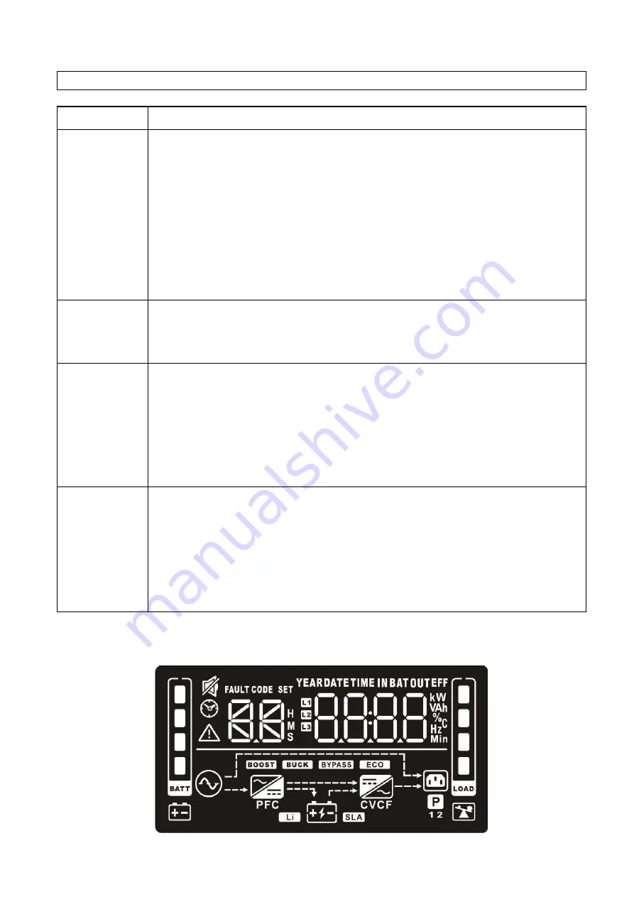
3-2. LCD Panel 


Содержание One V9 1.5K RT

Страница 1: ...Version 1 2 One V9 PF1 0 1K 1 5K 2K 3K Online UPS for Rack and Tower Systems User Manual...

Страница 2: ...ALLTRONIC GmbH Raiffeisenstra e 11 89438 Holzheim Service Hotline 49 9075 95 88 3 28...

Страница 3: ...2 Operating principle 5 2 3 Install the UPS Only for RT Models 5 2 4 Setup the UPS 6 2 5 Battery Replacement Only for RT Models 9 2 6 Battery Kit Assembly Option for RT Models 10 3 Operations 13 3 1...

Страница 4: ...by any individuals with no previous experience Connect the UPS system only to an earthed shockproof outlet which must be easily accessible and close to the UPS system Please use only VDE tested CE ma...

Страница 5: ...y occur between the battery terminals and the ground Before touching please verify that no voltage is present Caution Do not dispose of batteries in a fire The batteries may explode Caution Do not ope...

Страница 6: ...This is a category C2 UPS product In a residential environment this product may cause radio interference in which case the user many be required to take additional measures only for 220 230 240 VAC sy...

Страница 7: ...he original package in a safe place for future use 2 1 Rear panel view One V9 Tower Models 1K 1 5K 2K 3K One V9 RT Models 1K 1 5K 2K 3K 1 Programmable outlets connect to non critical loads 2 Output re...

Страница 8: ...ains input EMI RFI filters rectifier PFC inverter battery charger DC to DC converter battery dynamic bypass and UPS output 2 3 Install the UPS Only for RT Models For safety consideration the UPS is sh...

Страница 9: ...he UPS indoors in a clean environment where it is away from window and door Maintain minimum clearance of 100mm in the bottom of the UPS to avoid dust and high temperature 2 Maintain an ambient temper...

Страница 10: ...gative pole of external battery connector in UPS Polarity misconnection will cause UPS internal fault It s recommended to add one breaker between positive pole of battery pack and positive pole of ext...

Страница 11: ...lure you may extend the backup time to critical devices by setting shorter backup time for non critical devices Step 4 Communication connection Communication port USB port RS 232 port Intelligent slot...

Страница 12: ...d software installation If there no screen shows 1 minute after inserting the CD please execute setup exe file for initiating software installation 2 Follow the on screen instructions to install the s...

Страница 13: ...ut the front panel back to the unit 2 6 Battery Kit Assembly Option for RT Models NOTE Please assemble battery kit first before installing it inside of UPS Please select correct battery kit procedure...

Страница 14: ...l battery terminals by following below chart Step 3 Step 4 Put assembled battery packs on one side of plastic shells as below chart Cover the other side of plastic shell as below chart Then battery ki...

Страница 15: ...her side of plastic shell as below chart Then battery kit is assembly well Battery kit for 6 Batteries 6 BP CH Step 1 Step 2 Remove adhesive tapes Connect all battery terminals by following below char...

Страница 16: ...or transfer to Bypass mode if the Bypass enable setting by pressing this button Select Button Switch LCD message Press this button to change the LCD message for input voltage input frequency input cur...

Страница 17: ...mbient temperature output voltage output frequency load current and load percent k kilo W watt V voltage A ampere percent centigrade degree Hz frequency Load information Indicates the load level by 0...

Страница 18: ...4 LCD display wordings index Abbreviation Display content Meaning ENA Enable DIS Disable ESC Escape HLS High loss LLS Low loss AO Active open AC Active close EAT Estimated autonomy time RAT Running a...

Страница 19: ...115 120 127 VAC models you may choose the following output voltage 100 presents output voltage is 100Vac 110 presents output voltage is 110Vac 115 presents output voltage is 115Vac 120 presents output...

Страница 20: ...V LLS Low loss voltage in ECO mode in parameter 2 For 200 208 220 230 240 VAC models the setting range in parameter 3 is from 7V to 24V of the nominal voltage Default 12V For 100 110 115 120 127 VAC m...

Страница 21: ...equency high loss point from 51Hz to 55HZ Default 53 0Hz For 60Hz output frequency models 61 65Hz setting the frequency high loss point from 61Hz to 65Hz Default 63 0Hz LLS Bypass low Frequency point...

Страница 22: ...ternal battery bank is connected 13 Maximum charger current setting Parameter 1 Parameter 2 Interface Setting Set up the charger maximum current For high voltage model with 24 36 48VDC 1 2 4 6 8 10 12...

Страница 23: ...ation transformer connection ENA If selected it s allowed to connect to an external output isolation transformer DIS If selected it s not allowed to connect to external output isolation transformer De...

Страница 24: ...hen the input voltage is within voltage regulation range UPS will bypass voltage to output for energy saving The UPS will also charge the battery at ECO mode Frequency Converter mode When input freque...

Страница 25: ...nding every 2 seconds Overload Sounding every second Over input current Sounding 2 beep every 10 seconds Battery is not connected Sounding every 2 seconds Over Charge Sounding every 2 seconds Site wir...

Страница 26: ...incorrectly connected Check if all batteries are connected well Fault code is shown as 27 on LCD display and alarm is continuously sounding Battery voltage is too high or the charger is fault Contact...

Страница 27: ...place the battery Fault code is shown as 2A on LCD display and alarm is continuously sounding The short circuit occurs on the charger output Check if battery wiring of connected external pack is in sh...

Страница 28: ...full charged battery 91 full charged battery ECO Mode 96 full charged battery Battery Mode 88 90 BATTERY Battery Type 12V 7AH 12V 9AH 12V 7AH 12V 9AH Numbers 3 3 6 6 Recharge Time 3 hours recover to 9...

Страница 29: ...Sinewave EFFICIENCY AC Mode 91 full charged battery ECO Mode 96 full charged battery Battery Mode 88 90 BATTERY Battery Type 12V 7AH 12V 9AH 12V 7AH 12V 9AH Numbers 3 3 6 6 Recharge Time 3 hours recov...

Страница 30: ...r or from ALLTRONIC Your Way to ALLTRONIC Headquarter to Germany ALLTRONIC GmbH Raiffeisenstr 11 D 89438 Holzheim Germany Telefon 49 9075 95 88 328 Mail service alltronic net de CostumerCenter https p...

Отзывы: