background image

GENERAL LOOP INSTALLATION GUIDELINES

The following loop installation guidelines are for installing typical driveway loops for access
control applications (i.e. parking gates, sliding gates, swing gates etc...) Always consult with
loop detector manufacturers for specific equipment guidelines. This will confirm that the
proper configuration and installation techniques are applied for your application.

Useful information about inductive loops:

A.

The typical sensing height is 2/3 of the shortest leg of loop (in feet)

Therefore a 4’ x 8’ loop typically has a detection height of 2.6’.

B.

The inductance of a conventional four-slide loop can be estimated

using the formula:

L = P x (T + T) / 4           Where L = Loop Inductance in microHenries

P = Loop Perimeter in feet
T = Number of turns of wire in saw slot

Therefore a 4’ x 8’ loop with 3 turns would be:

L=(4 + 8 + 4 + 8) x (3  + 3) / 4
L=24 x (9 + 3) / 4
L=24 x 12 / 4
L=24 x 3
L=72 microHenries

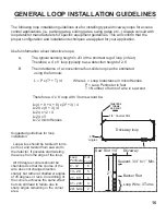
2

2

}

2’’

1/4’’

Saw Slot

Loop Wire: 3 Turns

Backer Rod

Sealant: 3/4’’ to 1’’ Min.

Driveway

Loop
Perimeter

# of
Turns

6’ - 12’

6

13’ - 20’

5

21’ - 60’

4

61’ - 240’’

3

241 & Up     2

Driveway loop

1/4’’ Feeder Slot

TWISTED 6

TURNS

PER FOOT

45

Angles

Suggested guidelines for loop
installation:

Loop wires should be twisted 6 turns

per foot, and twisted from saw slot to
the detector. If possible start twisting
the wires from the edge of the loop.

All 90 degree corners should be

chamfered so that the course of the
wire does not change direction
sharply but rather at shallower angles
of 45 degrees or less. Core drilling of
the corners achieves the same effect
but can still lead to failure due to
sharp edges remaining in the corner
area.

16

Содержание SW-300DC

Страница 1: ...UL325 compliant compliant UL991 L I S T E D US SW 350DC SW 300DC Installation Manual Copyright 2008 all o matic inc www allomatic net WWW ALLOMATIC NET Pending...

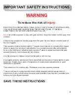
Страница 2: ...ading edge installation Three button station Magnetic Solenoid lock installation Master Slave connections Important safety instructions Different UL 325 class types Concrete pad Specs for SW 300DC Con...

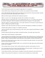
Страница 3: ...vates the non contact sensors After adjusting the force or the limit travel retest the gate operator Failure to adjust and retest the gate operator properly can increase the risk of injury Use the eme...

Страница 4: ...ll allow for reliable gate operation Install the operator inside the fence line do not install the operator on the public side of fence line Install a proper electrical ground to a gate operator Contr...

Страница 5: ...d to service the general public A vehicular gate operator intended for use at a guarded industrial location or building such as airport security areas or other restricted access locations not servicin...

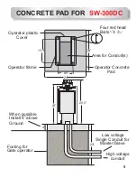
Страница 6: ...3 25 5 Operator plastic Cover Operator frame 1 2 1 2 Four red head Bolts X 3 Area for Conduit s Operator Concrete Pad When possible Install 4 above Ground Footing for Gate operator Master Slave Single...

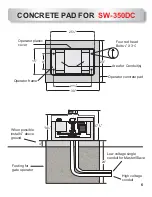
Страница 7: ...astic cover Operator frame 1 2 1 2 Four red head Bolts X 3 Area for Conduit s Operator concrete pad When possible install 4 above ground Footing for gate operator Low voltage single conduit for Master...

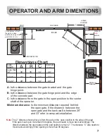
Страница 8: ...e point Is the distance between the gate hinge point and the edge of the concrete pad Is the distance from the gate in the open position to the center shaft of the operator Is the minimum distance req...

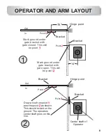
Страница 9: ...be point Y Mark ground under gate bracket with gate open This will be point Z 14 A Center shaft of Operator 1 2 X X Point Y Point Y Point Z Point Z Out In Out In OPERATOR AND ARM LAYOUT Draw a line fr...

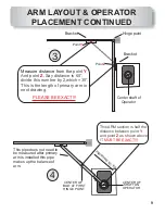
Страница 10: ...ich 30 This is the length of primary arm in next drawing PLEASE BE EXACT 4 This ARM section is half the distance between point and point as shown above Y Z IT MUST BE EXACT This pipe does not need to...

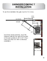
Страница 11: ...8 35 SECONDARY HINGE CENTER 27 20 Use these measurements only if the distance between the wall and the gate in the open position is 20 to 34 If you have more than 34 refer to standard installation To...

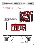
Страница 12: ...02 602 S26 S26 S 602 602 S26 S26 S CMX 309FB C CMX 309FB C 8 0000 M 8 0000 M 535202 535202 IR2110S IR2110S 0618 0618 IOR IOR IR2110S IR2110S 0618 0618 IOR IOR IR2110S IR2110S 0618 0618 IOR IOR ATMEL A...

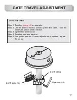
Страница 13: ...Use an allen wrench to loosen up the limit cams Turn the limit Cams to desired direction Step 3 tighten the allen screw Step 4 Turn the operator back on Step 5 Run gate operator If more adjustment is...

Страница 14: ...1 1501 476E 900R3 476E 900R3 107A 911C0 F MOC8050 629Q MAGNECRAFT W107DIP 3 5W 01 I0615 I O O 710 KE 710 KE 710 KE 710 KE 710 KE 710 KE 710 KE 710 KE 710 KE 710 KE 710 KE 710 KE SS 14 SS 14 SS 14 829B...

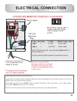
Страница 15: ...cedures DO NOT NEVER MUST ELECTRICAL CONNECTION 120 Volt Electrical Plug Power connection 115VAC 220VAC Single Phase LINE 1 LINE 2 ground rod 115V N 220V LINE 1 115V HOT 220V LINE 2 Connect to Use a p...

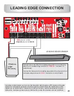
Страница 16: ...s from your exit point of the saw cut all the way to the circuit board no exceptions normally closed contacts normally open contacts from SWINGER LOOP LAYOUT Outside Safety loop Inside Safety loop Cen...

Страница 17: ...in microHenries P Loop Perimeter in feet T Number of turns of wire in saw slot Therefore a 4 x 8 loop with 3 turns would be L 4 8 4 8 x 3 3 4 L 24 x 9 3 4 L 24 x 12 4 L 24 x 3 L 72 microHenries 2 2 2...

Страница 18: ...ORMALLY CLOSED CONTACT C COMMON N C N O The circuit board output provides up to mAmps of power for accessories More than two or three accessories will require a separate power supply Accessories only...

Страница 19: ...This diagram is for the relay wires of the safety devices two wires to the board connections one from each device and two wires to the orange wire nut Wire nut Safety wire connections Remove jumper f...

Страница 20: ...DI Diablo Controls H2 LMA 1500 LP DSP 40S OFF OFF ON Exit Loop Loop Loop Safety Phantom 24VAC 12VDC Ground Exit Phantom Safety 19 To wire one or multiple safety devices in use with loop rack safety de...

Страница 21: ...nsor such as one that transmits radio frequency RF signals to the gate operator for entrapment protection functions shall be located where the transmission of the signals are not obstructed or impeded...

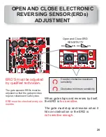
Страница 22: ...sier when setting limit switches and adjusting ERDs N O N O PED SW Jumper OU R N 3 8 6 B S 3 1 3 OU R N 3 8 6 B S 3 1 3 OU R N 3 8 6 B S 3 1 3 PHILIPS PHILIPS PHILIPS 72CB74K G4 Ls14 72CB74K G4 Ls14 C...

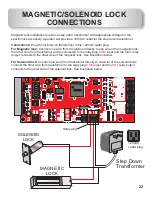
Страница 23: ...of the solenoid lock connect the other wire from transformer to the relay plug input and the relay output connects to the other wire of the solenoid lock See illustration below Connections For Magnet...

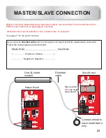
Страница 24: ...her test and adjust limit switches and the ERDs for each operator as machines All accessories must be installed on the master board no exception the stand alone See page 27 for dip switch settings Con...

Страница 25: ...1002 1002 1002 1002 1002 1002 2001 2001 2001 4750 4750 145 1212 4021 2491 2491 2262 2402 9531 4750 1131 1332 1001 1001 1001 20M 1001 1001 1001 1001 1001 1001 0022 1001 90R9 90R9 90R9 10R0 10R0 10R0 10...

Страница 26: ...LMC64 82AIM C8RB LMC64 82AIM C8RB LMC64 82AIM C8RB LMC64 82AIM 58ADC1K G4 Ls07 58ADC1K G4 Ls07 1001 1001 1001 1001 1001 1210 1001 1001 1001 1001 1002 1002 1002 1002 1002 1002 1002 1002 1002 1002 1002...

Страница 27: ...LMC64 82AIM C8RB LMC64 82AIM 58ADC1K G4 Ls07 58ADC1K G4 Ls07 1001 1001 1001 1001 1001 1210 1001 1001 1001 1001 1002 1002 1002 1002 1002 1002 1002 1002 1002 1002 1002 1002 1002 2001 2001 2001 4750 475...

Страница 28: ...the position the gate will open until one car passes the safety loops then it will stop and close If a second car pulls on the loop the gate will stop the car must then back off the loop before the g...

Страница 29: ...al 3 Push gate open lightly to the right to hold pedal down in position See page 11 for emergency release of SW 300 Operator SAFETY EXIT 115VAC AUTOMATIC GATE OPERATORS AUTOMATIC GATE OPERATORS AUTOMA...

Страница 30: ...1501 1501 1501 1501 1501 1501 1501 1501 1501 476E 900R3 476E 900R3 107A 911C0 F MOC8050 629Q MAGNECRAFT W107DIP 3 5W 01 I0615 I O O 710 KE 710 KE 710 KE 710 KE 710 KE 710 KE 710 KE 710 KE 710 KE 710...

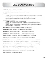
Страница 31: ...d or motor sensors Are not responding or disconnected LED will be on while limit nut is against open limit switch LED will be on while limit nut is against close limit switch LED will be on while oper...

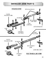
Страница 32: ...RTS PIPE KNUCKLES 3 SET SCREWS QUICK QUICK RELEASE ARM RELEASE ARM SECONDARY PIPE ARM HUB HUB PRIMARY PRIMARY FLAT BAR ARM ARM FLAT BAR GATE BRACKET GATE BRACKET SECONDARY END ROUND ARM RECTANGULAR AR...

Отзывы: