background image

507787-01

Issue 2007

Page 18 of 22

Checkout Procedures

NOTE: 

Refer  to  outdoor  unit  installation  instructions  for 

system  start-up  instructions  and  refrigerant  charging 

instructions. 

Pre-Start-Up Checks 

• 

Is the air handler properly and securely installed?

• 

 If horizontally configured, is the unit sloped up to 5/8 

inch toward drain lines?

• 

Will the unit be accessible for servicing?

•   Has an auxiliary pan been provided under the unit 

with separate drain for units installed above a finished 

ceiling or in any installation where condensate overflow 

could cause damage?

•   Have ALL unused drain pan ports been properly 

plugged?

• 

 Has  the  condensate  line  been  properly  sized,  run, 

trapped, pitched, and tested?

• 

 Is  the  duct  system  correctly  sized,  run,  sealed,  and 

insulated?

• 

Have all cabinet openings and wiring been sealed?

• 

 Is the indoor coil factory-installed TXV or RFC properly 

sized for the outdoor unit being used?

• 

Have all unused parts and packaging been disposed 

of?

• 

Is the filter clean, in place, and of adequate size?

• 

 Is the wiring neat, correct, and in accordance with the 

wiring diagram?

• 

Is the unit properly grounded and protected (fused)?

• 

Is  the  thermostat  correctly  wired  and  in  a  good 

location?

• 

Are all access panels in place and secure?

Check Blower Operation

1. 

Set thermostat to FAN ON. The indoor blower should 

come on.

Check Cooling Operation

1. 

 Set thermostat to force a call for cooling (approximately 

5ºF lower than the indoor ambient temperature).

2. 

 The outdoor unit should come on immediately and the 

indoor blower should start between 30 - 60 seconds 

later.

3. 

 Check the air flow from a register to confirm that the 

system is moving cooled air.

4. 

 Set  the  thermostat  5ºF  higher  than  the  indoor 

temperature.  The  indoor  blower  and  outdoor  unit 

should cycle off.

Check Electric Heat (If Used)

1. 

 Set thermostat to call for auxiliary heat (approximately 

5°F above ambient temperature). The indoor blower 

and auxiliary heat should come on together. Allow a 

minimum of 3 minutes for all sequencers to cycle on.

2. 

 Set  the  thermostat  so  that  it  does  not  call  for  heat. 

Allow up to 5 minutes for all sequencers to cycle off.

Operation

Time Delay Relay

Blower time delay operation:

1. 

 When cooling demand is initiated, there is a 1 second 

motor-on delay.

2. 

 After  the  motor-on  delay  expires,  motor  ramps  up 

to  100%  and  runs  at  100%  until  cooling  demand  is 

satisfied.

3. 

 Once  demand  is  met,  motor  runs  at  100%  for  45 

seconds.

4. 

Motor ramps down to stop.

1

SECOND

DELAY

OFF

100%

CFM

100%

CFM

45

SECS

COOLING

DEMAND

1

2

3

4

Figure 19. Blower Time Delay

Cooling (Cooling Only or Heat Pump) 

When the thermostat calls for cooling, 24 volts is put on 

the blower time-delay relay coil and then the indoor blower 

relay energizes. The normally open contacts close, causing 

the indoor blower motor to operate. The circuit between R 

and Y is completed, closing the circuit to the contactor in 

the outdoor unit, starting the compressor and outdoor fan 

motor. 

On heat pumps, circuit R and O energizes the reversing 

valve,  switching  the  valve  to  the  cooling  position.  (The 

reversing valve remains energized as long as the 

thermostat selector switch is in the COOL position.) 

At the completion of the cooling demand the indoor blower 

and outdoor unit should cycle off. Air handler should cycle 

off 45 seconds after the outdoor unit shuts off. 

Heating (Electric Heat Only) 

When the thermostat calls for heat, the circuit between R 

and W is completed, and the heat sequencer is energized. 

A time delay follows before the heating elements and the 

indoor  blower  motor  come  on.  Units  with  a  second  heat 

sequencer can be connected with the first sequencer to W 

on the thermostat sub-base, or they may also be connected 

to a second stage on the sub-base. 

Содержание BCE5C Series

Страница 1: ...8 Operation 18 Repairing or Replacing Cabinet Insulation 19 Professional Maintenance 20 Homeowner Maintenance 20 Improper installation adjustment alteration service or maintenance can cause property damage personal injury or loss of life Installation and service must be performed by a licensed professional HVAC installer or equivalent service agency or the gas supplier WARNING The Clean Air Act of...

Страница 2: ...4 121 4 3 8 111 2 3 8 60 CONDENSATE DRAINS 2 Upflow and Downflow SUCTION LINE CONDENSATE DRAIN PIPING PLATE 3 2 1 4 x 3 3 4 BCE5C Unit Dimensions Upflow Inches mm Dimensions 018 024 030 036 042 048 060 in mm in mm in mm in mm in mm in mm A 43 1 2 1105 45 1 2 1156 47 1194 53 5 8 1362 55 1397 59 3 4 1518 B 18 1 2 470 18 1 2 470 18 1 2 470 21 1 2 546 21 1 2 546 21 1 2 546 C 16 1 2 419 16 1 2 419 16 1...

Страница 3: ...fore starting the installation In addition to conforming to manufacturer s installation instructions and local municipal building codes installation of air handler units with or without optional electric heat MUST conform with National Fire Protection Association NFPA standards Standard for Installation of Air Conditioning and Ventilation Systems NFPA No 90A and Standard for Installation of Reside...

Страница 4: ...e air handler evaporator coil supply fan assembly and duct system must be thoroughly cleaned following final construction clean up All air handler operating conditions must be verified according to these installation instructions EQUIPMENT MAY EXPERIENCE PREMATURE COMPONENT FAILURE AS A RESULT OF FAILURE TO FOLLOW THE ABOVE INSTALLATION INSTRUCTIONS FAILURE TO FOLLOW THE ABOVE INSTALLATION INSTRUC...

Страница 5: ... coil may tip into the drain pan once it is clear of the cabinet Support the coil when removing it IMPORTANT NOTE When the unit is installed in horizontal applications a secondary drain pan is recommended Refer to local codes NOTE This unit may be installed in left hand or right hand air discharge horizontal applications Adequate support must be provided to ensure cabinet integrity Ensure that the...

Страница 6: ...r The 90º bend must be on the same side as the horizontal drain pan as illustrated in Detail A in Figure 5 NOTE Be very careful when reinstalling the screws into the coil end plate engaging holes Misaligned screws may damage the coil 9 From the upflow position flip cabinet 90º to the left and set into place Replace blower assembly Secure coil in place by bending down the tab on the cabinet support...

Страница 7: ...heet metal screws 14 If suspending the unit it must be supported along the entire length of the cabinet If using chain or strap use a piece of angle iron or sheet metal attached to the unit either above or below so that the full length of the cabinet is supported Use securing screws no longer than 1 2ʺ to avoid damage to coil or filter as illustrated in Figure 3 Connect return and supply air plenu...

Страница 8: ...m Insulate the drain lines where sweating could cause water damage Test Condensate Drain Test the drain pan and drain line after installation 1 Pour several quarts of water into drain pan Use enough water to fill both the drain trap and the line 2 Check the installed drain pan Drain pan must be draining completely Drain line fittings must not be leaking Water must be draining from the end of the p...

Страница 9: ...n the summer resulting in an increase in the number of service calls Before using any filter with this system check the specifications provided by the filter manufacturer against the data given in the appropriate Product Specifications Additional information is provided in Service and Application Note ACC002 August 2000 IMPORTANT Installing Duct System Connect supply air duct to the flange on top ...

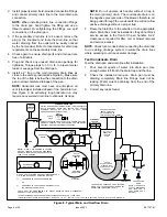
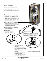
Страница 10: ...SION VALVE CAPILLARY TUBE IS NOT TOUCHING METAL EDGES OR COPPER TUBING REMOVE RUBBER PLUG FROM BOTH LIQUID AND SUCTION LINES NOTE BCE5C SERIES UNITS USE NITROGEN OR DRY AIR AS A HOLDING CHARGE IF THERE IS NO PRESSURE WHEN THE RUBBER PLUGS ARE REMOVED CHECK THE COIL FOR LEAKS BEFORE INSTALLING EITHER REMOVE OR PUSH PIPE WRAPPING BACK THROUGH HOLE IN PIPING PLATE BEFORE LINE SET CONNECTION AND BRAZI...

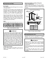
Страница 11: ...e set is required contact Technical Services NOTE Sealing the Unit Seal the unit so that warm air is not allowed into the cabinet Warm air introduces moisture which results in water blow off problems This is especially important when the unit is installed in an unconditioned area If installed in an unconditioned space sealant should be applied around the electrical wires refrigerant tubing and con...

Страница 12: ...s in accordance with tables 310 16 and 310 17 in the National Electric Code ANSI NFPA No 70 or tables 1 through 4 in the Canadian Electric Code Part I CSA Standard C22 1 The power supply must be sized and protected according to the specifications supplied on the product This air handler is factory configured for 240 volt single phase 60 cycles For 208 volt applications see 208 Volt Conversion late...

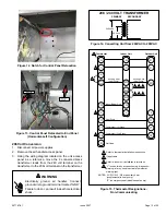
Страница 13: ...result in death or electrical shock WARNING 208 240 VOLT TRANSFORMER PRIMARY SECONDARY 240 Volts 208 Volts Figure 14 Converting Unit from 240VAC to 208VAC Figure 15 Thermostat Designations Non Communicating 1 Refer to thermostat installation instructions 2 If applicable 3 Refer to indoor unit installation instructions 4 L is used for any accessories e g diagnostic warning alarm used to activate th...

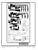
Страница 14: ...507787 01 Issue 2007 Page 14 of 22 4KW 5KW Figure 16 Typical Wiring Diagram BCE5C Air Handler with Electric Heat PSC 018 024 030 036 042 models ...

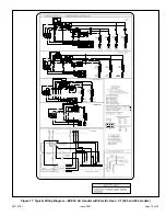
Страница 15: ...507787 01 Issue 2007 Page 15 of 22 4KW 5KW Figure 17 Typical Wiring Diagram BCE5C Air Handler with Electric Heat CT 048 and 060 models ...

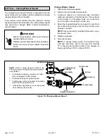
Страница 16: ...oling blower speed is factory configured to provide correct air flow for an outdoor unit that matches the cooling capacity rating of the air handler If the outdoor unit is smaller than the maximum cooling capacity rating for the air handler the cooling blower speed may need to be changed Refer to blower performance chart in Table 4 Electric shock hazard Disconnect all power supplies before servici...

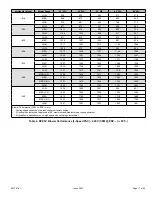
Страница 17: ...52 1390 1345 HIGH 1816 1756 1693 1605 1528 048 LOW 1257 1212 1157 1116 1053 MED LOW 1486 1448 1411 1364 1330 MED 1721 1675 1630 1594 1553 MED HIGH 1721 1675 1630 1594 1553 HIGH 1840 1794 1754 1721 1681 060 LOW 1098 1049 1001 926 831 MED LOW 1624 1594 1565 1520 1492 MED 1815 1783 1758 1730 1685 MED HIGH 1903 1869 1837 1809 1764 HIGH 1981 1957 1923 1893 1861 Blower Performance CFM vs ESP in w c Cool...

Страница 18: ...cycle off Check Electric Heat If Used 1 Set thermostat to call for auxiliary heat approximately 5 F above ambient temperature The indoor blower and auxiliary heat should come on together Allow a minimum of 3 minutes for all sequencers to cycle on 2 Set the thermostat so that it does not call for heat Allow up to 5 minutes for all sequencers to cycle off Operation Time Delay Relay Blower time delay...

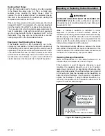
Страница 19: ... unit is put back into operation Insulation loses its insulating value when wet damaged separated or torn IMPORTANT Matte or foil faced insulation is installed in indoor equipment to provide a barrier between outside air conditions surrounding ambient temperature and humidity and the varying conditions inside the unit If the insulation barrier is damaged wet ripped torn or separated from the cabin...

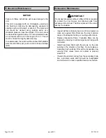
Страница 20: ...nance Do not operate system without a filter A filter is required to protect the coil blower and internal parts from excessive dirt and dust The filter is placed in the return duct by the installer IMPORTANT Inspect air filters at least once a month and replace or clean as required Dirty filters are the most common cause of inadequate heating or cooling performance Replace disposable filters Clean...

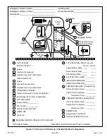
Страница 21: ...ing Mode Return Duct Temperature ___________ THERMOSTAT Adjusted and Programmed Return External Static ______ ______ Total External Static ______ ______ 6 Supply Duct Temperature ___________ Temperature Drop ___________ TEMPERATURE RISE Heating Mode Return Duct Temperature __________ Supply Duct Temperature __________ Temperature Rise __________ Operation Explained to Owner 9 Explained Operation o...

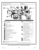
Страница 22: ...______ Total External Static ______ ______ 6 6 Supply Duct Temperature ___________ Temperature Drop ___________ TEMPERATURE RISE Heating Mode Return Duct Temperature __________ Supply Duct Temperature __________ Temperature Rise __________ Operation Explained to Owner 9 Electric Heat Amps 7 Explained Operation of System to Homeowner Technician s Name _______________________Date Start Up Performanc...

Отзывы: