

507787-01
Issue 2007
Page 6 of 22
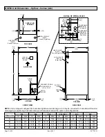
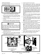
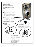
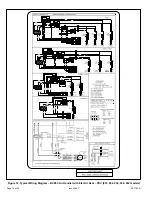
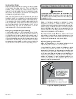
Left-Hand Air Discharge
For horizontal left-hand air discharge, the following field
modifications are required.
SPLASH GUARD (-60 MODEL)
DOWN-FLOW RAIL
FRONT EDGE OF HORIZONTAL
DRAIN PAN
DRIP
SHIELD
Figure 4.
Left-Hand Discharge Configuration
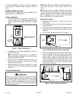
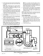
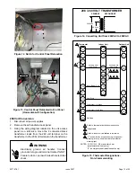
1.
Remove access panels and the corrugated padding
between the blower and coil assembly. Discard the
corrugated padding.
2.
Pull the coil assembly from unit. Pull off the horizontal
drain pan.
3.
Remove the drain plugs from back drain holes on
horizontal drain pan and reinstall them on front holes.
After removal of drain pan plug(s), check drain hole(s)
to verify that drain opening is fully open and free of any
debris. Also check to make sure that no debris has
fallen into the drain pan during installation that may plug
up the drain opening.
IMPORTANT
4.
Rotate drain pan 180º front-to-back and install it on the
opposite side of the coil.
5.
Remove screws from top cap. Remove drip shield
screw located in the center of the back coil end seal
as illustrated in Detail A in Figure 5.
6.
Rotate drip shield 180° front-to-back.
7.
Remove plastic plug from left hole on coil front end
seal and reinstall plug in back hole. Reinstall drip
shield screw in front coil end seal. Drip shield should
drain downward into horizontal drain pan inside coil.
8.
Rotate top cap 180º front-to-back and align with
unused screw holes. Holes must align with front and
back coil end plates (see Detail B in Figure 5). The top
cap has a 45º bend on one side and a 90º bend on the
other.
The 90º bend must be on the same side as
the horizontal drain pan
as illustrated in Detail A in
NOTE:
Be very careful when reinstalling the screws
into the coil end plate engaging holes. Misaligned
screws may damage the coil.
9.
From the upflow position, flip cabinet 90º to the left
and set into place. Replace blower assembly. Secure
coil in place by bending down the tab on the cabinet
support rail as illustrated.
NOTE:
Seal around the exiting drain pipe, liquid and
suction lines to prevent infiltration of humid air.
10.
Install the splash guard (-060 model) on the front edge
of the horizontal drain pan as shown in Figure 4.
NOTE:
For horizontal applications in high humidity
areas, remove the downflow rail closest to the drain
pan. To remove rail, remove screw from rail at back
of unit and at cabinet support rail. Remove downflow
rail then replace screws. Also, seal around the exiting
drain pipe, liquid and suction lines to prevent infiltration
of humid air.
11.
Knock out drain seal plate from access door. Secure
plate to cabinet front flange with screw provided.
12.
Flip access door and replace it on the unit.
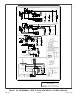
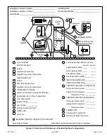
Figure 5.
Field Modification for Left-Hand Discharge
90º
BEND
CABINET
SUPPORT
TOP CAP
SCREWS
DRAIN PAN
REINSTALLED
HERE
DRAIN PAN
SHIPPING
LOCATION
TOP CAP ROTATED TO
CORRECT POSITION
———— DRAIN PLUGS ————
REINSTALLED HERE REMOVED FROM HERE
BACK COIL
END SEAL
TOP CAP
90º
BEND
INSTALL DRAIN PAN
BETWEEN TAB AND
EXTERIOR INNER WALL.
DETAIL A
DETAIL B
DETAIL C
FRONT VIEW
3/16” PLASTIC
PLUG (REAR COIL
END SEAL)
ALIGN HOLES WITH
HOLES IN COIL END
PLATE. STARTING WITH
THE ROUND HOLES ON
THIS END.
DRIP SHIELD
SCREW (FRONT
COIL END SEAL)
DRIP
SHIELD
COIL SHOWN IN UPFLOW POSITION FOR EASY
CONVERSION (
LEFT-HAND AIR DISCHARGE
)


