background image

507335-02

Page 37 of 39

Issue 2001

Planned Service

The following items should be checked during an annual inspection. Power to the unit must be shut off for the service 

technician’s safety.

Fresh air grilles and louvers

  (on  the  unit  and  in  the 

room where the furnace is installed) - Must be open and 

unobstructed to provide combustion air. 

Burners

 - Must be inspected for rust, dirt, or signs of water. 

Vent pipe

 - Must be inspected for signs of water, damaged 

or sagging pipe, or disconnected joints. 

Unit appearance

 - Must be inspected for rust, dirt, signs of 

water, burnt or damaged wires, or components. 

Blower access panel

  -  Must  be  properly  in  place  and 

provide a seal between the return air and the room where 

the furnace is installed. 

Return air duct

 - Must be properly attached and provide 

an air seal to the unit. 

Operating performance

 - Unit must be observed during 

operation  to  monitor  proper  performance  of  the  unit  and 

the vent system. 

Combustion gases

 - Flue products must be analyzed and 

compared to the unit specifications. 

Problems  detected  during  the  inspection  may  make  it 

necessary to temporarily shut down the furnace until the 

items can be repaired or replaced. 

Instruct the homeowners to pay attention to their 

furnace. 

Situations  can  arise  between  annual  furnace 

inspections  that  may  result  in  unsafe  operation.  For 

instance, items innocently stored next to the furnace may 

obstruct  the  combustion  air  supply.  This  could  cause 

incomplete  combustion  and  the  production  of  carbon 

monoxide gas. 

Repair Parts List

The following repair parts are available from the local distributor. When ordering parts, include the complete furnace model 

number and serial number which are printed on the rating plate located on the furnace. All service must be performed by a 

licensed professional installer (or equivalent), service agency, or gas supplier.

Cabinet Parts

• 

Heating compartment access panel

• 

Blower access panel

•  Top cap

Control Panel Parts

•  Transformer
• 

Two-stage, variable speed integrated control

• 

Door interlock switch

Blower Parts

• 

Blower wheel

• 

Blower housing

• 

Motor

• 

Motor electronics

• 

Power Choke (1 hp only)

• 

Motor mounting frame

• 

Blower housing cutoff plate

Heat Parts

• 

Flame sensor

• 

Heat exchanger assembly

• 

Gas Manifold

• 

Two speed combustion air inducer

• 

Two stage gas valve

• 

Main burner cluster

• 

Main burner orifices

• 

Pressure switch

• 

Ignitor

• 

Primary limit control

• 

Flame rollout switch

• 

Secondary limit

Содержание 80G2UH070AV12

Страница 1: ... installation adjustment alteration service or maintenance can cause property damage personal injury or loss of life Installation and service must be performed by a licensed professional installer or equivalent service agency or the gas supplier WARNING As with any mechanical equipment personal injury can result from contact with sharp sheet metal edges Be careful when you handle this equipment WA...

Страница 2: ...eft 5 3 8 137 Right 1 9 16 40 Left 33 838 3 1 8 79 1 15 16 49 14 356 9 16 14 3 76 Right 6 3 4 171 Left 2 FLUE OUTLET Either Side 3 OPTIONAL EXTERNAL SIDE RETURN AIR FILTER KIT Either Side 16 406 14 3 4 375 3 OPTIONAL EXTERNAL SIDE RETURN AIR FILTER KIT Either Side 3 1 4 83 5 8 16 1 3 1 4 83 23 3 4 603 25 635 3 4 19 Front Panel AIR FLOW ELECTRICAL INLET Either Side Unit Dimensions Capacity A B C D ...

Страница 3: ...TROL BOX BLOWER ASSEMBLY BURNER ACCESS PANEL BURNER BOX GAS VALVE COMBUSTION AIR INDUCER PRESSURE SWITCH COMBUSTION AIR INDUCER HEAT EXCHANGER CABINET BLOWER ACCESS PANEL INCLUDES INTEGRATED CONTROL AND TRANSFORMER ROLLOUT LOCATED INSIDE BURNER BOX Figure 1 ...

Страница 4: ... current National Fuel Gas Code Vent installations must be consistent with the venting tables in this instruction and applicable provisions of local building codes This furnace is CSA International certified for installation clearances to combustible material as listed on the unit nameplate and in the tables in Figure 8 and Figure 11 Installers should also consider the greater of either accessibil...

Страница 5: ...heating is prohibited d The input rate and temperature rise must be set per the furnace rating plate e Supply and Return air ducts must be provided and sealed to the furnace Return air must be terminated outside of the space where furnace is installed f Return air temperature range between 60 F 16 C and 80 F 27 C must be maintained g MERV 11 or greater air filters must be installed in the system a...

Страница 6: ...quire air for the combustion process If sufficient combustion air is not available the furnace or other appliances will operate inefficiently and unsafely Enough air must be provided to meet the needs of all fuel burning appliances and appliances such as exhaust fans which force air out of the house When fireplaces exhaust fans or clothes dryers are used at the same time as the furnace much more a...

Страница 7: ...enclosure and one opening within 12 inches 305 mm of the bottom See Figure 3 Air from Outside If air from outside is brought in for combustion and ventilation the confined space must have two permanent openings One opening shall be within 12 inches 305 mm of the top of the enclosure and one opening within 12 inches 305 mm of the bottom These openings must communicate directly or by ducts with the ...

Страница 8: ...back of the furnace Doing so will adversely affect the operation of the safety control devices which could result in personal injury or death WARNING The gas furnace can be installed as shipped in either the upflow position or the horizontal position Select a location that allows for the required clearances that are listed on the unit nameplate Also consider gas supply connections electrical suppl...

Страница 9: ...and the platform to ensure that the furnace operates properly and safely The furnace is equipped with a removable bottom panel to facilitate installation Markings are provided on both sides of the furnace cabinet for installations that require side return air Cut the furnace cabinet at the maximum dimensions shown on Page 2 NOTE 20C and 20D units that require air volumes over 1800 cfm 850 L s must...

Страница 10: ...ply and return air plenums must be supported separately NOTE When the furnace is installed on a platform in a crawlspace it must be elevated enough to avoid water damage and to allow the evaporator coil to drain Figure 12 Optional Return Air Base Upflow Applications Only For use with A B C and D cabinets FRONT VIEW 1 Unit side return air Opening SIDE VIEW 3 1 4 83 1 23 584 Overall Maximum 584 23 3...

Страница 11: ...The base must provide a stable support and an airtight seal to the furnace Allow absolutely no sagging cracks gaps etc The return and supply air duct systems must never be connected to or from other heating devices such as a fireplace or stove etc Fire explosion carbon monoxide poisoning personal injury and or property damage could result WARNING Filters This unit is not equipped with a filter or ...

Страница 12: ...and the platform to ensure that the unit operates properly and safely Use fiberglass sealing strips caulking or equivalent sealing method between the plenum and the furnace cabinet to ensure a tight seal If a filter is installed size the return air duct to fit the filter frame Venting A 4 inch diameter flue transition is factory installed on the combustion air inducer outlet of all models Figure 1...

Страница 13: ...the pressure switch assembly Remove pressure switch assembly 1 screw and cut wire tie to free pressure switch wires Reinstall pressure switch on the other side of orifice plate and reconnect pressure switch hose Resecure pressure switch wires Either pull excess wires through the blower compartment and secure using supplied wire tie or coil excess wire and secure to the gas manifold Figure 20 Horiz...

Страница 14: ...I Z223 1 and are provided as a guide for proper vent installation Proper application termination construction and location of vents must conform to local codes having jurisdiction In the absence of local codes the NFGC serves as the defining document Refer to the tables and the venting information contained in these instructions to properly size and install the venting system Once the venting syst...

Страница 15: ...st first be lined with either type B1 vent or an insulated single wall flexible vent lining system which has been sized according to the provided venting tables and the vent pipe manufacturer s instructions IMPORTANT A fan assisted furnace may be commonly vented into an existing lined masonry chimney if the following conditions are met The chimney is currently serving at least one drafthood equipp...

Страница 16: ...ommon venting Tables 5 6 7 and 8 were generated using a maximum horizontal vent connector length of 1 1 2 feet 46 m for each inch 25 mm of connector diameter as follows Table 2 Connector Diameter in mm Maximum Horizontal Connector Length ft m 3 76 4 1 2 1 37 4 102 6 1 83 5 127 7 1 2 2 29 6 152 9 2 74 7 178 10 1 2 3 20 11 If the common vertical vent is offset the maximum common vent capacity listed...

Страница 17: ...g steps shall be followed for each appliance connected to the venting system being placed into operation while all other appliances connected to the venting system are not in operation 1 Seal any unused openings in the common venting system 2 Inspect the venting system for proper size and horizontal pitch Determine that there is no blockage restriction leakage corrosion or other deficiencies which...

Страница 18: ... 15 136 20 226 22 339 5 22 65 30 130 39 219 49 330 10 29 59 40 121 51 206 64 315 15 35 53 48 112 61 195 75 301 20 0 0 97 0 202 0 349 0 540 2 10 75 14 149 18 250 20 377 5 21 71 29 143 38 242 47 367 10 28 64 38 133 50 229 62 351 15 34 58 46 124 59 217 73 337 20 48 52 55 116 69 206 84 322 30 0 0 100 0 213 0 374 0 587 2 9 81 13 166 14 283 18 432 5 21 77 28 160 36 275 45 421 10 27 70 37 150 48 262 59 4...

Страница 19: ...8 69 57 136 80 225 115 337 5 51 63 75 128 102 216 144 326 10 NR NR 95 116 128 201 182 308 15 NR NR NR NR 158 186 220 290 20 0 35 96 54 200 78 346 114 537 2 37 74 56 148 78 248 113 375 5 50 68 73 140 100 239 141 363 10 NR NR 93 129 125 223 177 344 15 NR NR NR NR 155 208 216 325 20 NR NR NR NR 186 192 254 306 30 0 34 99 53 211 76 372 110 584 2 37 80 55 164 76 281 109 429 5 49 74 72 157 98 271 136 41...

Страница 20: ...92 52 146 69 220 15 1 21 50 33 89 47 142 64 220 2 22 53 35 96 49 153 66 235 3 24 55 36 102 51 163 68 248 20 1 21 54 33 99 46 157 62 246 2 22 57 34 105 48 167 64 259 3 23 60 35 110 50 176 66 271 30 1 20 62 31 113 45 181 60 288 2 21 64 33 118 47 190 62 299 3 22 66 34 123 48 198 64 309 Common Vent Capacity Type B Double Wall Vents with Type B Double Wall Connectors Serving Two or More Category I Appl...

Страница 21: ... 60 77 110 112 175 169 278 2 51 62 81 115 117 185 177 290 3 54 64 85 119 122 193 185 300 NOTE Single appliance venting configurations with zero lateral lengths are assumed to have no elbows in the vent system For all other vent configurations the vent system is assumed to have two 90 elbows For each additional 90 elbow or equivalent for example two 45 elbows equal one 90 elbow beyond two the maxim...

Страница 22: ...380 35 052 1400 39 64 950 26 90 770 21 80 660 18 69 580 16 42 530 15 01 490 13 87 460 13 03 430 12 18 400 11 33 1 1 2 38 1 1 610 40 894 2100 59 46 1460 41 34 1180 33 41 990 28 03 900 25 48 810 22 94 750 21 24 690 19 54 650 18 41 620 17 56 2 50 8 2 067 52 502 3950 111 85 2750 77 87 2200 62 30 1900 53 80 1680 47 57 1520 43 04 1400 39 64 1300 36 81 1220 34 55 1150 32 56 2 1 2 63 5 2 469 67 713 6300 1...

Страница 23: ...LACK IRON PIPE ONLY TO BE ROUTED INSIDE OF CABINET Figure 26 Upflow Applications Possible Gas Piping Configurations GROUND JOINT UNION DRIP LEG MANUAL MAIN SHUT OFF VALVE GROUND JOINT UNION DRIP LEG MANUAL MAIN SHUT OFF VALVE GROUND JOINT UNION DRIP LEG MANUAL MAIN SHUT OFF VALVE Horizontal Application Left Side Air Discharge Horizontal Application Right Side Air Discharge FIELD PROVIDED AND INSTA...

Страница 24: ...es can be damaged if subjected to pressures greater than 1 2 psig 3 48 kPa 14 inches w c IMPORTANT Figure 28 Electrical ELECTROSTATIC DISCHARGE ESD Precautions and Procedures Electrostaticdischargecanaffectelectroniccomponents Take precautions during furnace installation and service to protect the furnace s electronic controls Precautions will help to avoid control exposure to electrostatic discha...

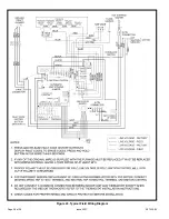
Страница 25: ...th the neutral leg of the circuit being connected to one of the provided neutral terminals See Figure 43 for control configuration This terminal is energized in the heating mode whenever the combustion air inducer is operating 9 Install the room thermostat according to the instructions provided with the thermostat If the furnace is being matched with a heat pump refer to the instruction packaged w...

Страница 26: ...s for heat See the furnace wiring diagram for specific connection information Electronic Air Cleaner Terminals are provided on the integrated ignition blower control board for connection of a 120 volt electronic air cleaner The EAC terminal is energized whenever the thermostat calls for heat cooling or continuous blower See furnace wiring diagram for specific connection information Variable Speed ...

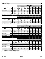
Страница 27: ...hes Each flash signifies 100 CFM count the flashes and multiply by 100 to determine the actual CFM delivered for example 10 flashes x 100 1000 CFM Adjust Tap Airflow amounts may be increased or decreased by 10 by moving the ADJUST jumper plug see Figure 32 from the NORM position to the or position Changes to the ADJUST tap will affect both cooling and heating airflows The TEST position on the ADJU...

Страница 28: ...urn Air Heating CFM 0 through 0 8 w c Cooling CFM 0 through 0 8 w c Model Motor Hp Stage Speed Adjustment Heat Setting A Heat Setting B Heat Setting C Heat Setting D Cool Setting A Cool Setting B Cool Setting C Cool Setting D 80G2UH070AV12 1 2 2nd Norm 707 890 925 1013 926 1003 1104 1213 1st Norm 673 750 864 949 689 726 795 859 80G2UH090BV16 1 2nd Norm 1013 1075 1130 1394 897 1158 1346 1499 1st No...

Страница 29: ...lve to the appliance before shutting off electrical supply WARNING Before attempting to perform any service or maintenance turn the electrical power to unit OFF at disconnect switch CAUTION During blower operation the ECM motor emits energy that may interfere with pacemaker operation Interference is reduced by both the sheet metal cabinet and distance WARNING BEFORE LIGHTING smell all around the a...

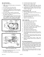
Страница 30: ...e unit if service is to be performed 3 Remove the heating compartment access panel 4 Move gas valve switch to OFF position Do not force See Figure 33 and Figure 34 5 Replace the upper access panel Failure to Operate If the unit fails to operate check the following 1 Is the thermostat calling for heat 2 Are access panels securely in place 3 Is the main disconnect switch closed 4 Is there a blown fu...

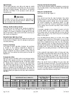
Страница 31: ...threaded plug on the inlet side of the gas valve provides access to the supply pressure tap Honeywell Valve 1 Remove the threaded plug 2 Install a field provided barbed fitting 3 Connect a manometer White Rodgers Valve 1 Loosen threaded plug removal not required 2 Connect a manometer See Table 15 for supply line pressure Replace or tighten the threaded plug after measurements have been taken Manif...

Страница 32: ...re 35 through Figure 39 Heating On a call for heat from the room thermostat the control board performs a 1 second self check Upon confirmation that the pressure switch contacts are in an open position the control energizes the combustion blower on high speed The control then checks for adequate combustion air by making sure the low fire pressure switch contacts are closed The igniter energizes and...

Страница 33: ...the selected cooling airflow for 1 minute then shuts off Two Stage Cooling A call for 1st stage cooling from the thermostat closes the R to Y circuit on the control board The control waits for a 1 second delay before energizing the circulating blower The blower motor runs at 57 of the selected air flow for the first 7 5 minutes of the 1st stage cooling demand passive dehumidification mode After 7 ...

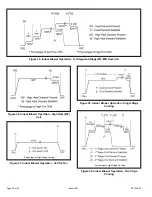
Страница 34: ...e W1 W2 Heat Call Figure 36 Indoor Blower Operation High Heat W2 Call Figure 37 Indoor Blower Operation Call for Fan Percentage of High Stage Cooling Figure 38 Indoor Blower Operation Single Stage Cooling Figure 39 Indoor Blower Operation Two Stage Cooling Percentage of High Stage Cooling ...

Страница 35: ... further lubrication is needed The blower access panel must be securely in place when the blower and burners are operating Gas fumes which could contain carbon monoxide can be drawn into living space resulting in personal injury or death WARNING Filters All filters are installed external to the unit Filters should be inspected monthly Clean or replace the filters when necessary to ensure that the ...

Страница 36: ... fault code is flashed last To clear the fault code history press and hold the pushbutton switch in for more than 5 seconds before releasing High Heat State LED On 80G2UH V models a green LED is provided on the control board to indicate high heat state see Table 18 CFM LED On 80G2UH V models equipped with a variable speed motor an amber LED is provided on the control board to display CFM To determ...

Страница 37: ...ly shut down the furnace until the items can be repaired or replaced Instruct the homeowners to pay attention to their furnace Situations can arise between annual furnace inspections that may result in unsafe operation For instance items innocently stored next to the furnace may obstruct the combustion air supply This could cause incomplete combustion and the production of carbon monoxide gas Repa...

Страница 38: ...507335 02 Page 38 of 39 Issue 2001 Figure 43 Typical Field Wiring Diagram ...

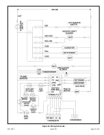
Страница 39: ...507335 02 Page 39 of 39 Issue 2001 Figure 44 Wiring Schematic ...

Отзывы: