


507335-02
Page 27 of 39
Issue 2001
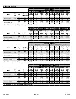
Circulating Airflow Adjustments
Cooling Mode
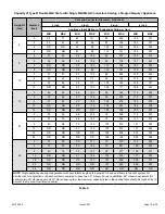
The units are factory set for the highest airflow for each
model. Adjustments can be made to the cooling airflow
by repositioning the jumper plug marked COOL – A, B,
C, D (see Figure 32) based on the information found in
the Adjusting Airflow tables. To determine what CFM the
motor is delivering at any time, count the number of times
the amber LED on the control board flashes. Each flash
signifies 100 CFM; count the flashes and multiply by 100
to determine the actual CFM delivered (for example: 10
flashes x 100 = 1000 CFM).
Heating Mode
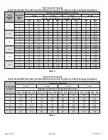
These units are factory set to run at the middle of the heating
rise range as shown on the unit rating plate. If higher or
lower rise is desired, reposition the jumper plug marked
HEAT - A, B, C, D (see Figure 32) based on the information
found in the Adjusting Airflow tables. To determine what
CFM the motor is delivering at any time, count the number
of times the amber LED on the control board flashes. Each
flash signifies 100 CFM; count the flashes and multiply by
100 to determine the actual CFM delivered (for example:
10 flashes x 100 = 1000 CFM).
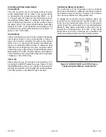
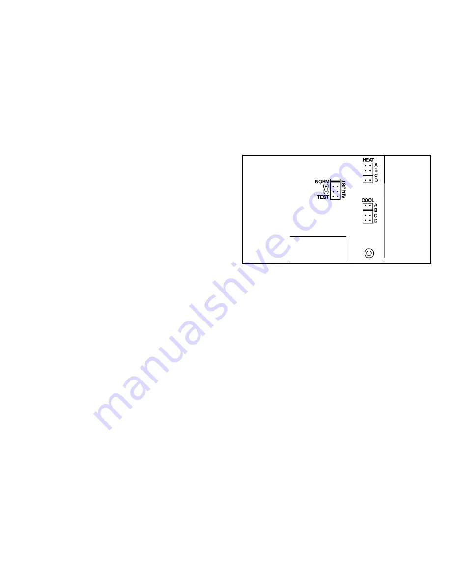
Adjust Tap
Airflow amounts may be increased or decreased by 10%
by moving the ADJUST jumper plug (see Figure 32) from
the NORM position to the (+) or (-) position. Changes to the
ADJUST tap will affect both cooling and heating airflows.
The TEST position on the ADJUST tap is not used.
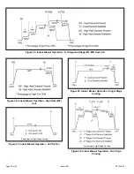
Continuous Blower Operation
The comfort level of the living space can be enhanced
when using this feature by allowing continuous circulation
of air between calls for cooling or heating. The circulation
of air occurs at half the full cooling airflow rate.
To engage the continuous blower operation, place the
fan switch on the thermostat into the ON position. A call
for fan from the thermostat closes R to G on the ignition
control board. The control waits for a 1 second thermostat
debounce delay before responding to the call for fan by
ramping the circulating blower up to 50% of the cooling
speed. When the call for continuous fan is satisfied, the
control immediately ramps down the circulating blower.
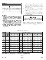
Figure 32. ADJUST, HEAT, and COOL Taps on
Integrated Ignition/Blower Control Board


