


508133-01
Page 19 of 25
Issue 2140
Unit Operation
4HP18V Unit Operation with a Conventional
24VAC Non-Communicating 2-Stage Thermostat
When the 4HP18V unit is installed with a conventional
24VAC non-communicating 2-stage thermostat, a Y1 first
stage heating or cooling demand will initiate heating or
cooling operation and first stage indoor blower operation.
The compressor will be controlled in the variable capacity
mode by varying the compressor capacity to obtain the
target suction pressure set point. The Y2 second stage
heating or cooling demand will initiate second stage blower
operation. Increased air volume will increase the load on
the indoor coil and increase the suction pressure. The
4HP18V compressor capacity will continue to be controlled
based upon the suction pressure. The unit capacity will be
controlled in the variable capacity mode throughout the
range of capacity from minimum capacity to maximum
capacity. If the Y2 demand remains after 20 minutes, the
4HP18V control will begin to ramp up the compressor
capacity until maximum capacity is achieved. The 4HP18V
unit will cycle off once the thermostat demand is satisfied.
4HP18V Unit Operation with a Conventional
24VAC Non-Communicating Single-Stage
Thermostat
When the 4HP18V unit is installed with a conventional
24VAC non-communicating single-stage thermostat,
a Y1 first stage heating or cooling demand will initiate
heating or cooling operation and heating or cooling indoor
blower operation. In single stage thermostat applications,
a jumper must be installed between Y1 and Y2 on the
4HP18V outdoor control. The compressor will be controlled
in the variable capacity mode by varying the compressor
capacity to obtain the target suction pressure set point. If
the heating or cooling demand remains after 20 minutes,
the 4HP18V control will begin to ramp up the compressor
capacity until maximum capacity is achieved. The 4HP18V
unit will cycle off once the thermostat demand is satisfied.
Heating Operation Mode Jumper
The Heating Operation Mode Jumper is only used on
applications installed with a conventional 24VAC non-
communicating heat pump thermostat. In applications
with a conventional 24VAC non-communicating heat
pump thermostat, the compressor capacity is controlled to
maintain the target liquid pressure setpoint. The Heating
Operation Mode Jumper has two selectable heating
modes. The two modes are Efficiency (Jumper installed
on Pins 1 & 2) and Comfort Mode (Jumper Removed).
The factory default position is the Efficiency Mode. The
Efficiency mode has a variable liquid pressure setpoint
that will vary with the outdoor temperature; as the outdoor
temperature decreases, the liquid pressure setpoint will
increase. When the Operation Mode jumper is installed
in the “Comfort Mode” the liquid pressure setpoint is 425
psig.
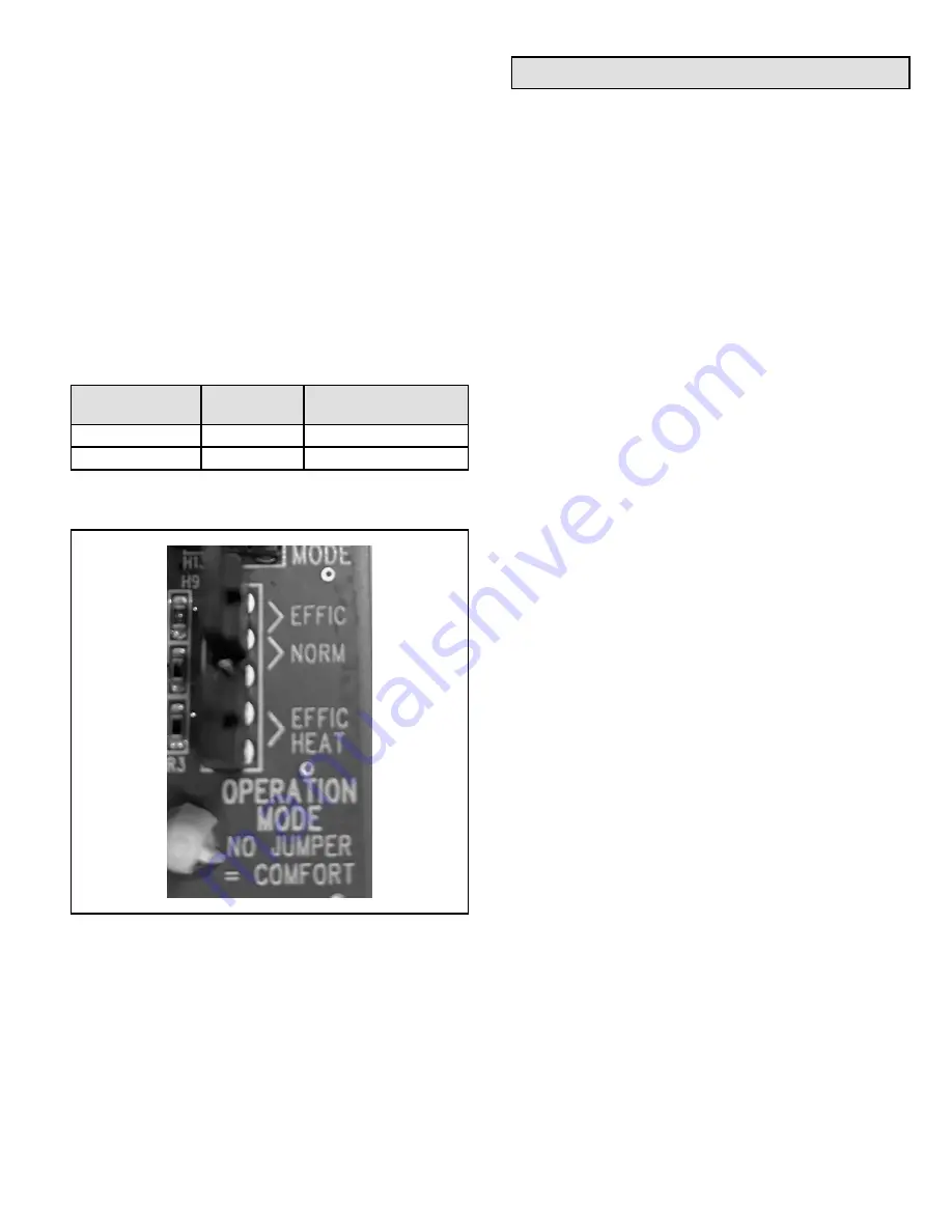
Operation Mode
Jumper
Jumper
Position
Target Liquid Pressure
Setting
Efficiency (default)
Pin 4 to Pin 5
Variable based on OAT
Comfort
Jumper Off
425 PSIG
Table 10. Heating Operation Mode Jumper
(Conventional 24VAC Thermostats Only)
Figure 12. Operation Mode Jumper