


Page 18 of 25
508133-01
Issue 2140
4. The unit will display the unit type for 10 seconds. Press
the push button and hold it for 3 seconds for the unit
to store the unit type. Once, the unit code is stored
the system acknowledges by displaying a string of
characters ending with the updated system unit code.
After programming of unit type is complete, the unit can be
set up for charge mode operation.
Charge Mode Jumper
To initiate the 4HP18V Charge Mode function, install the
jumper across the two Charge Mode Pins (CHRG MODE)
on the outdoor control. The Charge Mode can be used
when charging the system with refrigerant, checking
the refrigerant charge, pumping down the system and
performing other service procedures that requires outdoor
unit operation at 100% capacity.
4HP18V
Charge Mode Operation with a Conventional
24VAC Non-Communicating Heat Pump Thermostat
Charge Mode Display String
When unit is in the charge mode, Suction Pressure
(SPxxx), Suction Temp (Stxx.x), Superheat (SHxx.x), Liquid
Pressure (LPxxx), Liquid Temp (Ltxx.x) and Subcooling
(SCxx.x) will be scrolled on the 7-segment display.
Example:
S P 1 3 5
pause
S t 6 2
pause
S H 1 5
pause
L P 3 4 5
pause
L t 9 6
pause
S C 1 0
repeat
Charge Mode Jumper Operation in the Cooling Mode
On applications with a conventional 24VAC non-
communicating heat pump thermostat, the charge mode
jumper must be installed on the Charge Mode Pins after
providing a cooling compressor demand to the 4HP18V
and an “O” cooling reversing valve demand to initiate the
Charge Mode. A cooling blower demand must also be
provided to initiate blower in high stage operation on the
indoor unit.
The compressor and outdoor fan motor will begin to ramp
up and reach 100% design capacity within 3 minutes. They
will continue to operate at 100% design capacity for the
duration of charge mode.
Charge Mode Jumper Operation in the Heat Pump
Heating Mode
On applications with a conventional 24VAC non-
communicating heat pump thermostat, the charge mode
jumper must be installed on the Charge Mode Pins after
providing a heating compressor demand to the 4HP18V
without an “O” reversing valve signal to initiate the Charge
Mode. A heating blower demand must also be provided to
initiate high speed blower operation on the indoor unit.
The compressor and outdoor fan motor will begin to ramp
up and reach 100% design capacity within 3 minutes. They
will continue to operate at 100% design capacity for the
duration of charge mode.
Exiting Charge Mode
To exit the charging mode, remove the Charge Mode
Jumper from the Charge Mode Pins. The system will
be in Charge Mode for a maximum time of 60 minutes
and will automatically exit the charge mode and resume
normal operation after 60 minutes even if the charge mode
jumper is left in place. To extend the charge mode beyond
60 minutes, ensure the cooling/heating demand, blower
demand and appropriate reversing valve demand are
available and reapply the charge mode jumper.
NOTE:
If compressor demand is lost during charge mode
period, then the compressor and fan will cease to operate,
and the unit will enter into a delay timer for 3 minutes.
Repeat the charging mode procedure to get back into
charge mode.
Cooling Operation Mode Jumper
The Cooling Operation Mode Jumper is only used on
applications installed with a conventional 24VAC non-
communicating heat pump thermostat. In applications
with a conventional 24VAC non-communicating heat
pump thermostat, the compressor capacity is controlled to
maintain the target suction pressure setpoint. The Cooling
Operation Mode Jumper has three selectable cooling
modes. The three modes are Efficiency (Jumper installed
on Pins 1 & 2), Normal Mode (Jumper installed on Pins 2
& 3) and Comfort Mode (Jumper Removed). The factory
default position is the Efficiency Mode. The Efficiency
mode has a variable suction pressure setpoint that will vary
with the outdoor temperature; as the outdoor temperature
increases the suction pressure setpoint will decrease.
When the Cooling Operation Mode jumper is installed in
the “Normal Mode” the suction pressure setpoint is 135
psig.
When the Cooling Operation Mode jumper is installed in
the “Comfort Mode” the suction pressure setpoint is 125
psig.
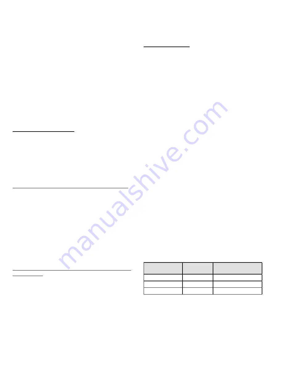
Operation Mode
Jumper
Jumper
Position
Target Suction
Pressure Setting
Efficiency (default)
Pin 1 to Pin 2
Variable based on OAT
Normal
Pin 2 to Pin 3
135 PSIG
Comfort
Jumper Off
125 PSIG
Table 9. Cooling Operation Mode Jumper
(Conventional 24VAC Thermostats Only)