507043-01
Issue 1222
Page 7 of 8
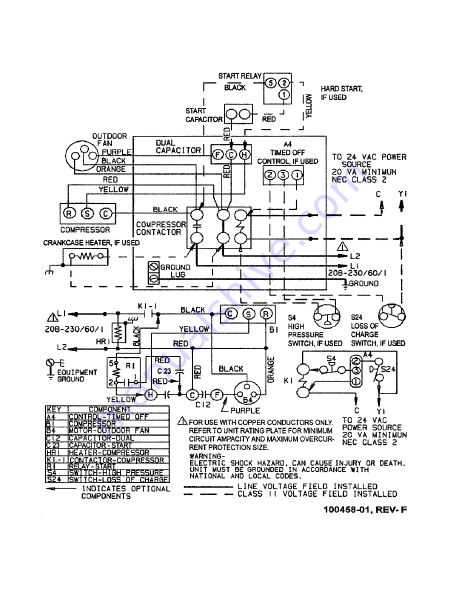
A/C SINGLE PHASE WIRING DIAGRAM
Страница 1: ...onal state or local codes in any way These instructions must be left with the property owner Manufactured By Allied Air Enterprises LLC A Lennox International Company 215 Metropolitan Drive West Columbia SC 29170 P507043 01 P 507043 01 4AC13 14 SPLIT SYSTEM AIR CONDITIONER INSTALLATION START UP INSTRUCTIONS HOMEOWNERS INFORMATION MANUAL TABLE OF CONTENTS These units are designed for use in residen...
Страница 2: ... approved indoor unit outdoor unit contains system refrigerant charge for operation with indoor unit of the same size when connected by 15 ft of field supplied tubing For proper unit operation check refrigerant charge using charging information located on control box cover IMPORTANT Maximum liquid line size is 3 8 in O D for all residential applications including long lines Outdoor Section Zoning ...
Страница 3: ...ervice side should be 24 and 48 on top On a solid level foundation or pad To minimize refrigerant line lengths DO NOT LOCATE THE UNIT On brick concrete blocks or unstable surfaces Near clothes dryer exhaust vents Near sleeping area or near windows Under eaves where water snow or ice can fall directly on the unit with clearance less than 2 ft from a second unit with clearance less than 4 ft on top ...
Страница 4: ...e a refrigerant leak detector to check all joints The system may also be checked for leaks using a halide torch or pressure and soapy solution After completion of leak check relieve all pressure from system before evacuation Evacuating And Charging Instructions These outdoor units are pre charged at the factory with adequate refrigerant to handle 15 feet of refrigerant tubing 1 Connect the vacuum ...
Страница 5: ...ns shipped with room thermostat Generally the thermostat should not be exposed to sunlight drafts or vibration and should not be mounted on exterior walls Low voltage connections should be in accordance to the wiring diagram Typical Low Voltage Connection Start Up Procedure 1 Close electrical disconnects to energize system 2 Set room thermostat at desired temperature Be sure set point is below ind...
Страница 6: ...low and add charge if superheat is high Units with Indoor TXV Units installed with cooling mode TXV require charging with the subcooling method 1 Operate unit a minimum of 10 minutes before checking charge 2 Measure liquid service valve pressure by attaching an accurate gage to service port Determine saturation temp from T P chart 3 Measure liquid line temperature by attaching an accurate thermist...
Страница 7: ...507043 01 Issue 1222 Page 7 of 8 A C SINGLE PHASE WIRING DIAGRAM ...
Страница 8: ...es can be drawn into coils by movement of the air Clogged condenser coils will lower the efficiency of your unit and could cause damage to the condenser Periodically debris should be brushed from the condenser coils Use a soft bristle brush with light pressure only DO NOT damage or bend condenser coil fins Damaged or bent fins may affect unit operation Painted Surfaces For maximum protection of th...