149
Alvium USB Cameras User Guide V3.6.4
Specifications
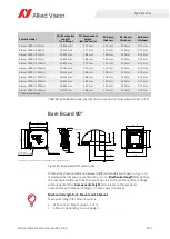
Bare Board 90°
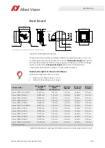
Dimensions that are common between different models are shown in
,
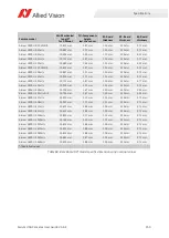
model specific dimensions are listed in
.
Mechanical length
(ML) defines
the mechanical distance from the mounting area to the lens mount front flange,
without optical filter.
Components height
(CH) relates to the electronic
components with maximum height, in some cases the sensor.
Alvium 1800 U-507m/c
19.929 mm
2.27 mm
1.25 mm
2.20 mm
3.75 mm
Alvium 1800 U-508m/c
19.929 mm
2.27 mm
1.25 mm
2.20 mm
3.75 mm
Alvium 1800 U-511m/c
19.613 mm
2.88 mm
1.00 mm
2.20 mm
3.75 mm
Alvium 1800 U-811m/c
19.613 mm
2.88 mm
1.00 mm
2.20 mm
3.75 mm
Alvium 1800 U-1236m/c
19.829 mm
2.27 mm
1.15 mm
2.20 mm
3.75 mm
Alvium 1800 U-1240m/c
19.763 mm
2.20 mm
1.15 mm
2.20 mm
3.75 mm
Alvium 1800 U-1242m/c
19.613 mm
2.88 mm
1.00 mm
2.20 mm
3.75 mm
Alvium 1800 U-1620m/c
19.613 mm
2.88 mm
1.00 mm
2.20 mm
3.75 mm
Alvium 1800 U-2040m/c
19.613 mm
2.88 mm
1.00 mm
2.20 mm
3.75 mm
Alvium 1800 U-2050m/c
19.663 mm
2.87 mm
1.05 mm
2.20 mm
3.75 mm
Alvium 1800 U-2460m/c
19.613 mm
2.88 mm
1.00 mm
2.20 mm
3.75 mm
*Theoretical values
Figure 45: Bare Board 90° dimensions
Mechanical length for S-Mount and CS-Mount
Mechanical length for other mounts is:
• CS-Mount: [C-Mount value] – 5 mm
• S-Mount: depending on your design.
Camera model
ML: Mechanical
length*
for C-Mount
CH: Components
height,
incl. the sensor
B1: Board
thickness
B2: Board
thickness
B3: Board
thickness
Table 68: Bare Board model specific dimensions and nominal values (sheet 2 of 2)
26.3
+
-
0.2
0.1
25
±0.1
25
±0.1
26.3
+
-
0.2
0.1
Sensor area
Do not mount here
DŽƵŶƟŶŐĂƌĞĂ
CH
7.7
A
26.4
+
-
0.2
0.1
26.4
+
-
0.2
0.1
22
±0.1
30.1
24.5
±0.1
26.3
26.4
B3 ± 10%
B1 ± 10%
B2 ± 10%
25
A (10 : 1)
IPSB
BAR
CODE
^ĞŶƐŽƌĂŶĚĞůĞĐƚƌŽŶŝĐĐŽŵƉŽŶĞŶƚƐĂƌĞƐĐŚĞŵĂƟĐƐĂŶĚǀĂƌLJďĞƚǁĞĞŶŵŽĚĞůƐ͘
DŽƵŶƟŶŐĂƌĞĂ
ML

