2075
22
S
FP
2
3
21
24
x610-24T
s
-POE+
4
6
8
10
12
3
5
1
2
7
9
11
1
3
15
17
19
21R
16
1
8
20
22R
24R
14
2
3
R
1000
/
100
SD
STATUS
FAULT
MASTER
RPS
PWR
PRES
MSTR
L/A
L/A
CLASS 1
LASER P
RODUCT
1
2
STACK
BU
S
Y
READY
FAULT
CON
S
OLE
2076
22
S
FP
2
3
21
24
x610-24T
s
-POE+
4
6
8
10
12
3
5
1
2
7
9
11
1
3
15
17
19
21R
16
1
8
20
22R
24R
14
2
3
R
1000
/
100
SD
STATUS
FAULT
MASTER
RPS
PWR
PRES
MSTR
L/A
L/A
CLASS 1
LASER P
RODUCT
1
2
STACK
BU
S
Y
READY
FAULT
CON
S
OLE
Chapter 3: Installing the Hardware
80
Figure 41. Attaching Rack-Mount Brackets
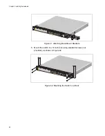
5. Mount the switch in a 19-inch rack using standard screws (not
provided), as shown in Figure 42.
Figure 42. Mounting the Switch in a Rack
Содержание x610 Series
Страница 8: ...Contents 8...
Страница 12: ...Tables 12...
Страница 120: ...Chapter 5 Troubleshooting 120...


