background image

x610 Series Layer 3 Gigabit Ethernet Switches Installation Guide

69

Steps to set up a 

VCStack

There are no set rules regarding the order in which stack configuration 
tasks need to be carried out. However, these steps provide a guideline to 
help ensure that the stack creation process goes smoothly.

1. Prepare the switches

Before connecting any of the switches together ensure that all switches 
have the same feature licences installed. If you have purchased feature 
licences to enable certain features to operate on the stack, then all stack 
members need to have the licences installed. If some stack members have 
feature licences installed for features that will not be used on the stack, 
and other switches do not have those licences installed, remove those 
unnecessary licences.

2. Install and power the stack master

Install and power up the master switch. It will detect that there are no other 
members in the stack, so it will elect itself master.

3. Install and power the backup member

Install the next switch, connecting the stacking cable from that switch to 
the master.

Note

Make sure the stacking cables are crossed over between the stack 
members. This means that stack port 1 on switch 1 should connect 
to stack port 2 on switch 2. If this is not done, the stack links will not 
come up and the stack will not form.

Power up the switch. It will detect that there is already an active master, 
and so will come up as a backup member. The active master will assign it 
the first available stack ID.

The active master will check that the new stack member has the same 
software version as itself. If the software versions are different, the active 
master will use the software auto-synchronization mechanism to force the 
new stack member to run the same software version.

4. Install and power the next backup member

Repeat step 3 for each of the other switches in the stack, remembering to 
connect port 2 of each new switch to port 1 of its neighbor. For last switch 
added to the stack, connect port 1 of this switch to port 2 of the first 
installed switch.

5. Confirm that the stack is operating

Check that the stack links have all come up successfully. This can be done 
by checking the LEDs on the switches. The port LEDs for all stack 

Содержание x610 Series

Страница 1: ...001664 Rev A x610 Series Layer 3 Stackable Gigabit Ethernet Switches x610 24Ts x610 24Ts X x610 48Ts x610 48Ts X x610 24SPs X x610 24Ts POE x610 24Ts X POE x610 48Ts POE x610 48Ts X POE Installation G...

Страница 2: ...their respective owners Allied Telesis Inc reserves the right to make changes in specifications and other information contained in this document without prior written notice The information provided...

Страница 3: ...tion of this equipment in a residential area is likely to cause harmful interference in which case the user will be required to correct the interference at his own expense Note Modifications or change...

Страница 4: ...ed Safety Statements Important The indicates that a translation of the safety statement is available in a PDF document Translated Safety Statements posted on the Allied Telesis website at www alliedte...

Страница 5: ...tch 21 x610 24Ts X Switch 22 x610 48Ts Switch 23 x610 48Ts X Switch 24 x610 24SPs X Switch 25 x610 24Ts POE Switch 26 x610 24Ts X POE Switch 27 x610 48Ts POE Switch 28 x610 48Ts X POE Switch 29 10 100...

Страница 6: ...Installation 88 Overview 88 Preparation 89 Installing a VCStack Stacking Module 89 Cabling an AT StackXG Stacking Module 93 Cabling an AT x6EM XS2 Stacking Module 94 Chapter 4 Cabling the Network Por...

Страница 7: ...g Chassis Configuration 119 Appendix A Technical Specifications 121 Physical Specifications 121 Environmental Specifications 122 Power Specifications 123 Certifications 124 RJ 45 Twisted Pair Port Pin...

Страница 8: ...Contents 8...

Страница 9: ...250 DC Power Supply 50 Figure 26 AT PWR800 Power Supply 50 Figure 27 AT PWR1200 Power Supply 50 Figure 28 Connectors on RPS 51 Figure 29 AT LBM Module Installed in x610 48Ts X Expansion Slot 53 Figure...

Страница 10: ...igure 63 Removing the Plastic Protector 93 Figure 64 Removing a Dust Plug from a SFP Slot 94 Figure 65 Installing an SFP Transceiver 94 Figure 66 Positioning the SFP Transceiver Locking Handle 95 Figu...

Страница 11: ...ATUS LED Descriptions 43 Table 10 STACK LED Descriptions 45 Table 11 SD LED Descriptions 47 Table 12 Class vs Power Levels 56 Table 13 PoE Ports Supported With AT PWR250 Power Supply Unit 57 Table 14...

Страница 12: ...Tables 12...

Страница 13: ...Layer 3 Gigabit Ethernet Switches This preface contains the following sections Product Documentation on page 14 Starting a Management Session on page 15 Safety Symbols Used in this Document on page 1...

Страница 14: ...the software features of the AlliedWare Plus Operating System Software which runs on the x610 Series Switches refer to AlliedWare Plus Operating System Software Reference Guide Virtual Chassis Stackin...

Страница 15: ...ions that describe how to start a local management session on a x610 switch refer to the Power Wiring to a DC AT PWR250 Power Supply Module on page 103 For information that describes how to log onto t...

Страница 16: ...s the safety symbols defined in Table 1 Table 1 Safety Symbols Symbol Meaning Description Caution Performing or omitting a specific action may result in equipment damage or loss of data Warning Perfor...

Страница 17: ...Where to Find Web based Guides The installation and user guides for all Allied Telesis products are available in portable document format PDF on our web site at www alliedtelesis com You can view the...

Страница 18: ...elesis com warranty for the specific terms and conditions of the warranty and for warranty registration Returning Products Products for return or repair must first be assigned a return materials autho...

Страница 19: ...Ds on page 45 Secure Digital SD LED on page 47 Terminal Port on page 48 Power Supplies on page 49 Redundant Power Supplies on page 51 AT LBM Loop Back Module on page 53 VCStack Stacking Module on page...

Страница 20: ...Layer 3 switches in the series x610 24Ts Switch x610 24Ts X Switch x610 48Ts Switch x610 48Ts X Switch x610 24SPs X Switch x610 24Ts POE Switch x610 24Ts X POE Switch x610 48Ts POE Switch x610 48Ts X...

Страница 21: ...r either an AT StackXG or an AT x6EM XS2 stacking module Fixed 120 watts power supply Figure 1 shows the x610 24Ts switch front and rear panels 22 SFP 23 21 24 4 6 8 10 12 3 5 1 2 7 9 11 13 15 17 19 1...

Страница 22: ...ng module Fixed 120 watts power supply Figure 2 shows the x610 24Ts X switch front and rear panel 22 SFP SFP 23 21 24 25 26 4 6 8 10 12 3 5 1 2 7 9 11 13 15 17 19 16 18 20 14 x610 24Ts X 10G 1000 100...

Страница 23: ...Figure 3 shows the x610 48Ts switch front and rear panel 48R 38 40 42 44 46R 2 4 6 8 10 12 34 36 32 26 28 30 16 14 22 24 18 20 SFP 47 45 47R 37 39 41 43 45R 1 3 5 7 9 11 15 13 17 19 21 23 33 31 35 25...

Страница 24: ...e 4 shows the x610 48Ts X switch front and rear panel POWER SUPPLY RPS READY RPS INPUT 12V 21A MAX STACKING WARNING This unit may have more than one power input To reduce the risk of electric shock di...

Страница 25: ...module Fixed 250 watts power supply Figure 5 shows the x610 24SPs X switch front and rear panel POWER SUPPLY RPS READY RPS INPUT 12V 21A MAX STACKING WARNING This unit may have more than one power in...

Страница 26: ...ply connector Expansion slot for either an AT StackXG or an AT x6EM XS2 stacking module Figure 6 shows the x610 24Ts POE switch front and rear panel 22 SFP 23 21 24 x610 24Ts POE 4 6 8 10 12 3 5 1 2 7...

Страница 27: ...supply PWR1200 Redundant power supply connector Expansion slot for either an AT StackXG or an AT x6EM XS2 stacking module Figure 7 shows the x610 24Ts X POE switch front and rear panel 22 SFP SFP 23 2...

Страница 28: ...her an AT StackXG or an AT x6EM XS2 stacking module Figure 8 shows the x610 48Ts POE switch front and rear panel 48R 38 40 42 44 46R 2 4 6 8 10 12 34 36 32 26 28 30 16 14 22 24 18 20 SFP 47 45 47R 37...

Страница 29: ...00 Redundant power supply connector AT LBM Loop Back module installed in the rear of the switch Figure 9 shows the x610 48Ts X POE switch front and rear panel 48R 38 40 42 44 46 2 4 6 8 10 12 34 36 32...

Страница 30: ...manually through the AlliedWare Plus Operating System Software Note In order for a switch port to successfully Auto Negotiate its duplex mode with a 10 or 100 Mbps end node the end node must also be...

Страница 31: ...This feature available when a port s speed and duplex mode are set through Auto Negotiation automatically configures a switch port to MDI or MDI X depending on the wiring configuration of the port on...

Страница 32: ...610 24Ts X x610 24Ts X POE x610 24SPs X x610 48Ts X and x610 48Ts X POE switches feature additional slots for optional Gigabit Ethernet SFP transceivers as listed in Table 2 The SFP slots support both...

Страница 33: ...x610 Series Layer 3 Gigabit Ethernet Switches Installation Guide 33 Note For a list of supported SFP and SFP transceivers contact your Allied Telesis sales representative...

Страница 34: ...ur combo ports as listed in Table 4 Table 4 10 100 1000Base T Ports Matched with SFP Slots on x610 48Ts and x610 48Ts POE Switches Ports and Slots Port 45R with SFP slot 45 Port 46R with SFP slot 46 P...

Страница 35: ...end node A 10 100 1000Base T port automatically transitions back to the active status when the link is lost on an SFP module In nearly all cases a 10 100 1000Base T port and an SFP module share the sa...

Страница 36: ...fer files between x610 switches 1319 SD Memory Card LOCK Figure 12 SD Card Note An SD card is not required for normal operations of the switch To insert an SD card position it so that the manufacturer...

Страница 37: ...k activity and D C duplex mode collisions Figure 13 shows the port LEDs on the non PoE models 1467 DUP COL LED LINK ACT LED LINK ACT LED DUP COL LED Figure 13 Port LEDs on non PoE x610 Series Switches...

Страница 38: ...10 or 100 Mbps D C Duplex Mode and Collisions Solid Green The port is operating in full duplex mode Solid Amber The port is operating in half duplex mode only applies when operating at 10 or 100 Mbps...

Страница 39: ...24SPs X x610 48Ts X and x610 48Ts X POE switches there is one LINK ACTIVITY LED as shown in Figure 16 and Figure 19 The SFP LED definitions are given in Table 7 and the SFP LED definitions are given i...

Страница 40: ...48 1000 100 SFP LINK ACT LEDs SFP 49 SFP 47 10G 1000 100 48 50 SFP LINK ACT LEDs SFP LINK ACT LEDs Chapter 1 Overview 40 Figure 17 SFP and SFP LEDs on x610 24SPs X Switch Figure 18 SFP LEDs on x610 4...

Страница 41: ...D Function State Description L A Link Status and Activity Off No link has been established between the port and the end node Solid Green The port has established a link at 1 Gbps Flashing Green Packet...

Страница 42: ...formation To locate these LEDs see Figure 20 On the rear panel there is a single system STATUS LED as shown in Figure 21 See Table 9 for a description of the system STATUS LEDs STATUS FAULT MASTER RPS...

Страница 43: ...3 Flashes This state indicates a chassis power supply fault and the chassis is powered by AT RPS3000 Redundant Power Supply This indication applies to all non POE and POE models 4 Flashes This state...

Страница 44: ...switch is not receiving power Solid Green The switch is receiving power RPS READY at rear Off The RPS is not receiving power Solid Green The RPS is receiving power Table 9 System STATUS LED Descriptio...

Страница 45: ...ACK Figure 22 Switch STACK LEDs Table 10 STACK LED Descriptions LED State Description MSTR Off The switch is not part of a stack or is a member unit of the stack Solid Green The switch is the master u...

Страница 46: ...port on another VCStack stacking module Flashing Green Stack Port 2 has established a link to a stacking port on another VCStack stacking module and is sending or receiving packet traffic PRES Off Th...

Страница 47: ...BUSY READY FAULT Table 11 SD LED Descriptions LED Function State Description SD Link Status and Activity Flashing Amber Indicates a fault has been detected The SD card is not valid or a read or write...

Страница 48: ...e port The terminal port has an RJ 45 style connector An RJ 45 to RS 232 management cable is supplied with the switch The terminal port is set to the following specifications Default baud rate 9600 bp...

Страница 49: ...PWR1200 is required to supply power to the PoE ports in addition to system power to the switch Warning Do not hot swap the power supply modules Always disconnect the AC cord before the power supply mo...

Страница 50: ...CTED AREA 40 60VDC 6A OUTPUT POWER FAULT AT PWR250 100 240VAC 12A MAX DC PWR FAULT AT PWR800 100 240VAC 16A MAX DC PWR FAULT AT PWR1200 2267 Chapter 1 Overview 50 Figure 25 AT PWR250 DC Power Supply F...

Страница 51: ...port up to four x610 switches simultaneously depending on the switches configuration The RPS can backup one high power consumption switch or two low power consumption switches with each power supply m...

Страница 52: ...ilable PoE power depends on the PoE rating of the associated power supply module in RPS If the switch is able to get PoE power from both primary power supply and RPS the primary power supply and the p...

Страница 53: ...ports If you need to configure the switch for stacking you may install a VCStack stacking module in place of the AT LBM Module POWER SUPPLY RPS READY RPS INPUT 56V 18A MAX 12V 21A MAX STACKING WARNIN...

Страница 54: ...peed of the AT x6EM XS2 is fixed at 10 Gbps AT StackXG STACK PORT 1 STACK PORT 2 AT x6EM XS2 1 2 L A L A POWER SFP SFP CLASS 1 LASER PRODUCT 10G LINK ACT 1000 LINK ACT L A Figure 30 AT StackXG Stackin...

Страница 55: ...on or off connect or disconnect the power cord For countries that require 100 125 VAC installations the power cord plug provided with the AT PWR1200 power supply has a 20 Amp 125 V NEMA 5 20P plug Th...

Страница 56: ...stor or capacitor is present the switch assumes that the device is a PD Once a PD is discovered a PSE may optionally perform PD classification by applying a DC voltage to the port If the PD supports o...

Страница 57: ...corresponding SFP combo port Power Capacity Either a 250W AT PWR250 800W AT PWR800 or a 1200W AT PWR1200 power supply can be installed in the x610 24Ts POE x610 24Ts X POE x610 48Ts POE and x610 48Ts...

Страница 58: ...10 48Ts POE 480W Max 16 ports Max 31 ports x610 48Ts X POE 480W Max 16 ports Max 31 ports Table 15 PoE Ports Supported With AT PWR1200 Power Supply Unit Model Available PoE Power IEEE 802 3at Class 4...

Страница 59: ...page 60 The Physical Stack on page 61 Resiliency Link on page 62 Resiliency Link Configurations via Switch Ports on page 63 Stack Formation on page 64 The Role of the Stack Master on page 64 Connecti...

Страница 60: ...link which is an extra out of band data link between stack members In the event of loss of communication across the stacking connection the stack members can determine the status of other members via...

Страница 61: ...is configuration the stack can still function using only a single high speed link Note that stacking ports labeled 1 must connect to stacking ports labeled 2 Also in this example the switches have AT...

Страница 62: ...A MAX STACKING WARNING This unit may have more than one power input To reduce the risk of electric shock disconnect both A C and RPS inputs before servicing unit 100 240VAC AT StackXG STACK PORT 2 AT...

Страница 63: ...attaching the switch ports to the VLAN For more information about the stack resiliency link refer to the Stacking Introduction and Stacking Commands chapters in the AlliedWare Plus Operating System So...

Страница 64: ...to automatically select which switch will become the stack master This selection is based on two components 1 The stack member s priority setting 2 The stack member s MAC address The master is the sw...

Страница 65: ...startup scripts Stack Management VLAN Managing the stack is the same as managing an individual switch You can connect to the asynchronous console port of any stack member or you can set an IP address...

Страница 66: ...atus within the stack are shown in Table 16 Table 16 STACK LED Descriptions LED State Description MSTR Off The switch is not part of a stack or is a member unit of the stack Solid Green The switch is...

Страница 67: ...cking ports when using L A 2 Off Stack Port 2 has not established a link to a stacking port on another VCStack stacking module Solid Green Stack Port 2 has established a link to a stacking port on ano...

Страница 68: ...tacking This feature allows x600 and x610 units to be stacked together to form a single stack Note that if a x610 switch is to be part of mixed mode VCStack then an AT StackXG must be installed in the...

Страница 69: ...onnecting the stacking cable from that switch to the master Note Make sure the stacking cables are crossed over between the stack members This means that stack port 1 on switch 1 should connect to sta...

Страница 70: ...k is not operating correctly The master or status LED will be green on the switch that is the stack master 6 Configure the stack as one switch You are now ready to configure the stack with channel gro...

Страница 71: ...leases differ between the stack members significantly then the stack master may not be able to upgrade the new switch automatically If this happens you should see a log message indicating incompatible...

Страница 72: ...ible even if mixed mode stacking is disabled on x610 Series switches For more information about stacking provisioning refer to the Stacking Introduction and Stacking Commands chapters in the AlliedWar...

Страница 73: ...er contains the following sections Reviewing Safety Precautions on page 74 Unpacking a Switch on page 77 Installing the Power Cord Retaining Clip on page 78 Installing the Switches in an Equipment Rac...

Страница 74: ...ty of electric shock disconnect electric power to the product before connecting or disconnecting the LAN cables E1 Warning Do not work on equipment or cables during periods of lightning activity E2 Wa...

Страница 75: ...ar le constructeur Les batteries doivent tre limin es conform ment aux instructions du constructeur E22 Warning Mounting of the equipment in the rack should be such that a hazardous condition is not c...

Страница 76: ...this device is located E40 Caution The unit does not contain field serviceable components Please return damaged units for servicing E42 Caution The Ethernet PoE ports are only intended for installatio...

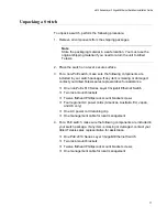
Страница 77: ...maged contact your Allied Telesis sales representative for assistance One non PoE x610 Series Layer 3 Gigabit Ethernet Switch Two rack mount brackets Twelve flathead Phillips rack mount bracket screws...

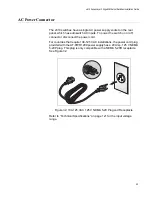
Страница 78: ...the power cord retaining clip on the switches 1 Locate the power cord retaining clip shown in Figure 38 100 240VAC Figure 38 Power Cord Retaining Clip 2 Install the clip on the AC power connector on...

Страница 79: ...the bottom of a switch You can leave the feet on 1 Place the switch upside down on a level secure surface 2 Using a flat head screwdriver remove the snap on plastic feet from the bottom of the switch...

Страница 80: ...22 SFP 23 21 24 x610 24Ts POE 4 6 8 10 12 3 5 1 2 7 9 11 13 15 17 19 21R 16 18 20 22R 24R 14 23R 1000 100 SD STATU S FAULT MASTE R RPS PWR PRES MSTR L A L A CLASS 1 LASER PRODUCT 1 2 STACK BUSY READY...

Страница 81: ...Figure 44 800W AT PWR800 power supply shown in Figure 45 on page 81 or a 1200W AT PWR1200 power supply shown in Figure 46 on page 82 can be installed in these switches The installation procedure is id...

Страница 82: ...4CPUCVR Note Store the packaging material in a safe location You must use the original shipping material if you need to return the unit to Allied Telesis 2 Remove the blank panel from the power supply...

Страница 83: ...is flush with the rear panel of the chassis as shown in Figure 48 through Figure 51 Light pressure may be needed to seat the module on the connector on the rear panel of the chassis Caution Do not for...

Страница 84: ...A RESTRICTED AREA 40 60VDC 6A OUTPUT POWER FAULT AT PWR250 2261 POWER SUPPLY RPS I 56V 18A MAX WARNING This unit may have more electric shock disconne unit 100 240VAC 12A MAX DC PWR FAULT AT PWR8000 C...

Страница 85: ...more electric shock disconne unit 100 240VAC 5A MAX DC PWR FAULT AT PWR250 x610 Series Layer 3 Gigabit Ethernet Switches Installation Guide 85 Figure 51 Installing the AT PWR1200 Power Supply Module 4...

Страница 86: ...N A RESTRICTED AREA 40 60VDC 6A OUTPUT POWER FAULT AT PWR250 2264 POWER SUPPLY RPS I 56V 18A MAX WARNING This unit may have more electric shock disconne unit 100 240VAC 12A MAX DC PWR FAULT AT PWR8000...

Страница 87: ...ide 87 Figure 55 Securing the AT PWR1200 Power Supply Module 5 If you are installing an AT PWR250 AT PWR800 or AT PWR1200 power supply module see AC Power Connection to a Power Supply Module on page 1...

Страница 88: ...ing modules are available The AT StackXG shown in Figure 56 has two full duplex 12 Gbps stacking ports The AT x6EM XS2 shown in Figure 57 has two 10 Gbps SFP stacking slots 1240 AT LX44CPUCVR AT Stack...

Страница 89: ...are supported in all x610 series products Note Do not install an AT StackXG or AT x6EM XS2 stacking module until you have read the latest version of the AlliedWare Plus Release Notes and the x610 Seri...

Страница 90: ...open slot allows dust to enter the unit and reduces proper airflow and cooling 3 Align the edges of either the AT StackXG or AT x6EM XS2 stacking module with the guides in the slot and carefully slid...

Страница 91: ...SER PRODUCT 10G LINK ACT L A x610 Series Layer 3 Gigabit Ethernet Switches Installation Guide 91 Figure 59 Installing the AT StackXG Stacking Module Figure 60 Installing the AT x6EM XS2 Stacking Modul...

Страница 92: ...PRODUCT 10G LINK ACT L A Chapter 3 Installing the Hardware 92 Figure 61 Securing the AT StackXG Stacking Module Figure 62 Securing the AT x6EM XS2 Stacking Module Note Do not cable the AT StackXG or...

Страница 93: ...on the stacking module and secure by tightening the two captive thumbscrews 3 Remove the plastic protector from the connector at the other end of the stacking cable and connect it to a Stack Port on...

Страница 94: ...LINK ACT L A RPS READY STACKING risk of rvicing AT LX44CPUCVR AT x6EM XS2 1 2 L A L A POWER SFP SFP CLASS 1 LASER PRODUCT 10G LINK ACT L A Figure 64 Removing a Dust Plug from a SFP Slot 2 Remove the...

Страница 95: ...llation Guide 95 5 Verify that the handle on the SFP transceiver is in the upright position as shown in Figure 66 to prevent inadvertently removing the transceiver Figure 66 Positioning the SFP Transc...

Страница 96: ...ptic Cable to the SFP Transceiver 8 Connect the other end of the stacking cable to a Stack Port on the stacking module in the next switch of the stack A stacking cable must crossover and connect to a...

Страница 97: ...the following sections Twisted Pair and Fiber Optic Specifications on page 98 Installing SFP and SFP Transceivers on page 100 Cabling the 10 100 1000Base T and Fiber Optic Ports on page 102 Power Wir...

Страница 98: ...0 m 328 ft 1000 Mbps Standard TIA EIA 568 A compliant Category 5 or TIA EIA 568 B compliant Enhanced Category 5 Cat 5e shielded or unshielded cabling with 100 ohm impedance and have a frequency range...

Страница 99: ...r 3 Gigabit Ethernet Switches Installation Guide 99 SFP and SFP Transceiver Specifications The specifications for optional SFP and SFP transceivers can be found on our Allied Telesis web site at www a...

Страница 100: ...u do remove the plug keep it for future use Unnecessary removal and insertion of a transceiver can lead to premature failure Warning A transceiver can be damaged by static electricity Be sure to obser...

Страница 101: ...al in a safe location 3 Position the transceiver with the label facing up if installing in a top slot and with the label facing down if installing in a bottom slot 4 Slide the transceiver into the slo...

Страница 102: ...re network devices can communicate with each other over more than one network path make sure that your switch is properly configured with the appropriate protocol s i e STP ESPR LACP etc Data loops wi...

Страница 103: ...Always be sure that the circuit breaker is in the OFF position before connecting the wires to the breaker E9 Warning For centralized DC power connection install only in a restricted access area E23 No...

Страница 104: ...l strip the three wires in the tray cable coming from the DC input power source to 8mm 1mm 0 31 in 0 039 in as shown in Figure 72 on page 104 Warning Do not strip more than the recommended amount of w...

Страница 105: ...the terminal block marked minus Warning Check to see if there are any exposed copper strands coming from the installed wires When this installation is done correctly there should be no exposed copper...

Страница 106: ...12 Turn the power supply module s On Off switch to On 13 Start a local management session on the unit by performing the procedure Starting a Local Management Session on page 109 Warning This unit mig...

Страница 107: ...igure 74 100 240VAC Figure 74 Power Cord Retaining Clip in the Up Position Note The AT PWR1200 power supply does not have a retaining clip 2 Plug the power cord into the AC power connector on the rear...

Страница 108: ...ons the power cord plug provided with the AT PWR1200 power supply has a 20 Amp 125 V NEMA 5 20P plug This plug is only compatible with a NEMA 5 20R receptacle See Figure 76 Figure 76 100 125 VAC 125 V...

Страница 109: ...on the front panel of the switch as shown in Figure 77 22 SFP 23 21 24 15 17 19 21R 16 18 20 22R 24R 23R 1000 100 SD STATUS FAULT MASTER RPS PWR PRES MSTR L A L A CLASS 1 LASER PRODUCT 1 2 STACK BUSY...

Страница 110: ...Chapter 4 Cabling the Network Ports 110 Warranty Registration For warranty information and registration go to the Allied Telesis web site at www alliedtelesis com support warranty...

Страница 111: ...stalled but the Status is Not Present on page 115 System Fault LED is Flashing on page 116 Cannot Establish a Local Out of Band Management Session on page 117 Switch Functions Intermittently on page 1...

Страница 112: ...following Make sure the power cord is securely connected to the power source and to the AC connector on the rear panel of the switch Verify that the power outlet has power by connecting another device...

Страница 113: ...speed and duplex mode manually the port defaults to MDI X Disabling Auto Negotiation may require manually configuring a port s MDI MDI X setting or using a crossover cable Make sure that the operating...

Страница 114: ...r an SFP transceiver refer to the installation instructions shipped with the module Check that the operating specifications for instance wavelength and maximum operating distance of the fiber optic po...

Страница 115: ...lled in a transceiver slot but the Uplink Information menu in the AlliedWare Plus Operating System Software interface displays Not Present for that port do the following Verify that the transceiver is...

Страница 116: ...e chassis is powered by AT RPS3000 Redundant Power Supply Contact Allied Telesis Technical Support for assistance See Contacting Allied Telesis on page 18 Five Flashes If the FAULT LED flashes five ti...

Страница 117: ...front panel do the following Check that the RJ 45 serial management cable is securely connected to the serial terminal port on the switch and to the RS 232 port on the terminal or personal computer C...

Страница 118: ...ittently If a switch functions intermittently check the system hardware status through the management interface Note the current voltage for the power supply compared to the optimum rating Verify that...

Страница 119: ...Stacking Chassis Configuration For information on issues with stacking refer to the Allied Telesis Inc website www alliedtelesis com for the Overview of Virtual Chassis Stacking VCS and the Virtual C...

Страница 120: ...Chapter 5 Troubleshooting 120...

Страница 121: ...419 mm 1 72 in x 17 34 in x 16 5 in x610 48Ts X 44 mm x 440 mm x 419 mm 1 72 in x 17 34 in x 16 5 in x610 24SPs X 44 mm x 440 mm x 419 mm 1 72 in x 17 34 in x 16 5 in x610 24Ts POE 44 mm x 440 mm x 4...

Страница 122: ...kg 16 75 lb x610 48Ts POE 7 82 kg 17 25 lb x610 48Ts X POE 8 50 kg 18 74 lb Recommended Minimum Ventilation on Front and Back Sides 100 mm 4 0 in Environmental Specifications Operating Temperature 0 C...

Страница 123: ...able 18 Maximum Power Consumption at Power Supply Output in Watts AT PWR250AC AT PWR250DC AT PWR800 AT PWR1200 Switch PoE Total Switch PoE Total Switch PoE Total x610 24Ts 70 W 70 W 70 W 70 W 70 W 70...

Страница 124: ...ectrical and Laser Safety EN60950 1 TUV EN60825 1 TUV UL 60950 1 CULUS CSA C22 2 No 60950 1 CULUS Quality and Reliability MTBF x610 24Ts 80 000 hrs x610 24Ts X 80 000 hrs x610 48Ts 70 000 hrs x610 48T...

Страница 125: ...in the MDI configuration at 10 or 100 Mbps Table 19 MDI Pin Signals 10 or 100 Mbps Pin Signal 1 TX 2 TX 3 RX 6 RX Table 20 lists the pin signal definitions when a port is operating in the MDI X confi...

Страница 126: ...ical Specifications 126 Table 21 lists the pin signal definitions when a port operating at 1000 Mbps Table 21 Pin Signals 1000 Mbps Pinout Pair 1 Pair 1 2 Pair 1 3 Pair 2 4 Pair 3 5 Pair 3 6 Pair 2 7...

Страница 127: ...l Port Pin Signals Pin Signal 1 Request to Send 2 Data Terminal Ready 3 Transmit Data 4 Data Carrier Detect 5 Ground 6 Receive Data 7 Data Set Ready 8 Clear to Send AT RPS3000 21 pin Connector Pinouts...

Страница 128: ...rved 5 12V Negative Remote Sense 6 RPS Power Good Active high from RPS to switch This signal is floating when cable is not connected 7 Reserved 8 56V Load Share for PoE Ready port only 9 56V Positive...

Отзывы: