background image


vi


ATENCION:  EL CABLE DE ALIMENTACION SE USA COMO UN DISPOSITIVO DE DESCONEXION.  PARA DESACTIVAR EL 
EQUIPO, desconecte el cable de alimentación.


INSTALACION


ELECTRICO—AUTO-AJUSTE DE TENSION
Este producto se ajustará automáticamente a cualquier tensión entre los valores máximos y mínimos indicados en la etiqueta.

ELECTRICO—EQUIPO DEL TIPO CLASE 1
ESTE EQUIPO TIENE QUE TENER CONEXION A TIERRA. El cable tiene que conectarse a un enchufe con tierra debidamente 
instalado.  Un enchufe que no está correctamente instalado podría ocasionar tensiones peligrosas en las partes metálicas están expuestas.

ELECTRICO—ADVERTENCIA SOBRE EL CABLE
Use un cable eléctrico con un máximo de 4,5 metros de largo, con una capacidad mínima de 6 amperios, 250 V, hecho de cable HAR, con el 
conector moldeado IEC 320 en un extremo y con un enchufe que está aprobado por el país de uso final en el otro.


INSTRUCCIONES DE MONTAJE


ATENCION:  Estos modelos están diseñados para operar en posición HORIZONTAL.  NO SE DEBEN MONTAR VERTICALMENTE 
sin el uso de un chasis de montaje vertical de Allied Telesyn que se ha diseñado para este fin.

ATENCION:  Las aberturas para ventilación no deberán bloquearse y deberán tener acceso libre al aire ambiental de la sala para su 
enfriamiento.

ATENCION:  NO separe las patas de goma del producto a menos que se esté usando un chasis de montaje vertical de Allied Telesyn.


TEMPERATURA REQUERIDA PARA LA OPERACIÓN


Este producto está diseñado para una temperatura ambiental máxima de 50 grados C.


PARA TODOS LOS PAÍSES:


  Monte el producto de acuerdo con los Códigos Eléctricos locales y nacionales.


ENERGIUTSTRÅLNING


Denna handelsprodukt har testats och befunnits vara i enlighet med U.S.A.s krav för klass A utrustning.


SÄKERHET


TILLKÄNNAGIVANDEN BETRÄFFANDE ELEKTRICITETSRISK:
RISK FÖR ELEKTRISK STÖT
För att undvika  ELEKTRISK stöt, ta ej av locket. Det finns inga delar inuti som behöver underhållas. Denna apparat är under 
HÖGSPÄNNING och får endast  öppnas av en utbildad kvalificerad tekniker. För att undvika ELEKTRISK STÖT, koppla ifrån produktens 
strömanslutning innan LAN-kablarna ansluts eller kopplas ur.

FARA FÖR BLIXTNEDSLAG
FARA:  ARBETA EJ på utrustningen eller kablarna vid ÅSKVÄDER.

VARNING: NÄTKABELN ANVÄNDS SOM STRÖMBRYTARE
FÖR ATT KOPPLA FRÅN STRÖMMEN, dra ur nätkabeln.


INSTALLATION


ELEKTRISKT—AUTOMATISK SPÄNNINGSJUSTERING
Denna  produkt justeras automatiskt till alla spänningar inom omfånget som indikeras på produktens märkning.

ELEKTRISKT—TYP KLASS 1 UTRUSTNING
DENNA UTRUSTNING MÅSTE VARA JORDAD. Nätkabeln måste vara ansluten till ett ordentligt jordat uttag. Ett felaktigt uttag kan 
göra att närliggande metalldelar utsätts för högspänning. Apparaten skall anslutas till jordat uttag, när den ansluts till ett nätverk.

ELEKTRISKT—ANMÄRKNING BETRÄFFANDE KABELN
Använd en kabel med maximum längd 4,5 meter och minimum 6 amp nominal, 250V, av HAR kabelfabrikat med ett specialutformat IEC 
320-kontaktdon i ena änden och i den andra en plugg som godkänts i landet där produkten används.


MONTERINGSINSTRUKTIONER


VARNING: Dessa modeller är konstruerade för användning i HORISONTALLÄGE.
VERTIKALMONTERING får EJ UTFÖRAS utan att ett Allied Telesyn specialkonstruerat vertikalt monteringschassi används.

VARNING: Luftventilerna får ej blockeras och måste ha fri tillgång till omgivande rumsluft för avsvalning. 

VARNING: Ta ej bort gummifötterna från produkten om inte ett Allied Telesyn vertikalt monteringschassi används.


DRIFTSTEMPERATUR


Denna produkt är konstruerad för rumstemperatur ej överstigande 50 grader Celsius. 


ALLA LÄNDER:


  Installera produkten i enlighet med lokala och statliga bestämmelser för elektrisk utrustning.

Attencion

!

Varning

Fara

!

Varning

!

Содержание CentreCOM AT-3012T

Страница 1: ...Allied Telesyn CentreCOM AT 3012T Multiport Repeater User Manual ...

Страница 2: ...uding but not limited to lost profits arising out of or related to this manual or the information contained herein even if Allied Telesyn International Corp has been advised of known or should have known the possibility of such damages Trademarks CentreCOM is a registered trademark of Allied Telesyn International Corp Ethernet is a registered trademark of Xerox Corporation UNIX is a registered tra...

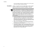
Страница 3: ...wer cord INSTALLATION ELECTRICAL AUTO VOLTAGE ADJUSTMENT This product will automatically adjust to any voltage between the ranges shown on the label ELECTRICAL TYPE CLASS 1 EQUIPMENT THIS EQUIPMENT MUST BE EARTHED Power plug must be connected to a properly wired earth ground socket outlet An improperly wired socket outlet could place hazardous voltages on accessible metal parts ELECTRICAL CORD NOT...

Страница 4: ...alleret jordforbunden stikkontakt En ukorrekt installeret stikkontakt kan sætte livsfarlig spænding til tilgængelige metaldele ELEKTRISK LEDNING Anvend ledning af maksimum 4 5 meters længde med en kapacitet på minimum 6 amp 250 v bestående af en IEC 320 connector med indstøbt HAR ledning i den ene ende og et stik i den anden ende godkendt der er af myndighederne i brugerlandet INSTRUKTIONER FOR OP...

Страница 5: ...CUIT POUR COUPER L ALIMENTATION DE L APPAREIL débranchez le cordon INSTALLATION ELECTRICITE REGLAGE DE TENSION AUTOMATIQUE Ce produit peut s ajuster automatiquement sur n importe quelle tension comprise dans la plage indiquée sur le label ELECTRICITE EQUIPEMENT DE CLASSE 1 CET APPAREIL DOIT ETRE MIS A LA TERRE La prise de courant doit être branchée dans une prise femelle correctement mise à la ter...

Страница 6: ...ne INSTALLAZIONE ELETTRICITÀ REGOLAZIONE AUTOMATICA DELLA TENSIONE Questo prodotto regolerà automaticamente la tensione ad un valore compreso nella gamma indicata sull etichetta ELETTRICITÀ DISPOSITIVI DI CLASSE 1 QUESTO DISPOSITIVO DEVE AVERE LA MESSA A TERRA La spina deve essere inserita in una presa di corrente specificamente dotata di messa a terra Una presa non cablata in maniera corretta ris...

Страница 7: ... DISPOSITIVO DE DESCONEXÃO PARA DESELETRIFICAR O EQUIPAMENTO desconecte o cabo de alimentação INSTALAÇÃO ELÉTRICO AJUSTE AUTOMÁTICO DE VOLTAGEM Este produto ajustar se á automaticamente a qualquer voltagem que esteja dentro dos limites indicados no rótulo ELÉTRICO EQUIPAMENTOS DO TIPO CLASSE 1 DEVE SER FEITA LIGAÇÃO DE FIO TERRA PARA ESTE EQUIPAMENTO O plugue deve ser conectado a uma tomada com li...

Страница 8: ...LKÄNNAGIVANDEN BETRÄFFANDE ELEKTRICITETSRISK RISK FÖR ELEKTRISK STÖT För att undvika ELEKTRISK stöt ta ej av locket Det finns inga delar inuti som behöver underhållas Denna apparat är under HÖGSPÄNNING och får endast öppnas av en utbildad kvalificerad tekniker För att undvika ELEKTRISK STÖT koppla ifrån produktens strömanslutning innan LAN kablarna ansluts eller kopplas ur FARA FÖR BLIXTNEDSLAG FA...

Страница 9: ... T 12 Port Repeater 1 Features 2 10BASE T UTP Cabling 3 Hub to MAU Wiring 3 Hub to Hub 3 Quick Installation Checklist 4 Setup 4 Testing 4 Chapter 2 Installation 5 Ventilation 5 Power 5 Setup 5 Connections 6 Chapter 3 Operations 7 Indicators 7 Front Panel Per Port 7 Front Panel Central 7 Back Panel 8 Segmentation Switches 8 System Check 8 ...

Страница 10: ...ing 9 Collision 9 Chapter 5 Configurations 11 Appendix A IEEE 802 3 Quick Primer 13 AUI Drop Cables 13 10BASE T 13 Thin 10BASE2 Ethernet 14 Thick 10BASE5 Ethernet 14 Propagation 14 Four Repeater Rule 14 Appendix B Glossary 15 ...

Страница 11: ...t regeneration which results in a higher performance network Packet regeneration includes regenerating preamble retiming of the data packets and extending collision fragments to ensure collision enforcement by all nodes These repeaters support IEEE compliant features along with additional functions which further ensure fault protection and proper network operation The IEEE 802 3 defined link integ...

Страница 12: ...rmits a maximum of four repeaters to be cascaded allowing over a thousand individual segments to be configured into a single network Features IEEE 802 3 compliant 10BASE T repeater Ethernet Version 1 0 and 2 0 compatible Supports all standard Ethernet media including fiber optic via AUI port One AUI and 12 RJ45 ports Standalone or department concentrator applications Automatic manual partitioning ...

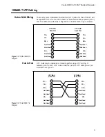
Страница 13: ...ded or linked together using UTP wiring If cascading of AT 3012T UTP Hubs is desired use the UTP cable pin out as illustrated in Figure 3 Figure 2 UTP MAU RJ45 Pin Diagram 1 2 3 4 5 6 7 8 1 2 3 4 5 6 7 8 TD TD RD Not Used TD TD RD Not Used Not Used Not Used Not Used Not Used Not Used Not Used RD RD UTP MAU RJ45 PIN UTP HUB RJ45 PIN Figure 3 UTP Hub RJ45 Pin Diagram 1 2 3 4 5 6 7 8 1 2 3 4 5 6 7 8 ...

Страница 14: ...ceiver 5 Attach a 10BASE T UTP cable with RJ45 connectors attached to 10BASE T port 1 If the AUI port is not used connect a second 10BASE T cable to port 2 6 Select the segmentation switch to the left default position for the connected ports Testing 1 Check the Link LED on the back panel for each 10BASE T port that is connected ON indicates a valid Link 2 Establish a network connection from the co...

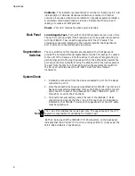
Страница 15: ...t the back panel Make absolutely sure that the voltage and frequency applied are of the correct values for your AT 3012T There is no external power switch for the AT 3012T UTP Hub Power is applied as soon as the power cord is connected Setup 1 Carefully remove the AT 3012T from its packaging materials Retain the packing materials until satisfactory installation has been achieved 2 Place the AT 301...

Страница 16: ...d Refer to the Chapter 1 10BASE T UTP Cabling of this manual for the correct wiring pinouts for Hub to Hub cables 1 Attach an RJ45 10BASE T UTP cable to port 1 Check the respective ports segment partition switch located on the front panel The slide switch should be set to the LEFT Auto position Port 1 Link LED should illuminate provided the 10BASE T transceiver on the opposite end of the UTP segme...

Страница 17: ...ual partitioning switch This switch enables you to manually partition a port For normal operation this switch needs to be in the Auto position Receive This LED flashes when incoming packets are present on the respective segment Front Panel Central Activity This LED indicates that the repeater is functional and is transmitting packets to all ports Figure 4 AT 3012T Front Panel Indicator ACTIVITY CO...

Страница 18: ...rtitioning switch Moving the slide switch to the Left position selects the port active Factory Default Moving the slide switch to the right segments the port from the others In the Right position the segmentation switch for the AUI port will disconnect the AT 3012T Hub from the attached transceiver System Check 1 Establish a connection from the device connected to port 1 to the device connected to...

Страница 19: ...le Level 3 or above designed for use in 10BASE T applications 10BASE T wiring lengths should not exceed 100 meters 328 ft The wiring should be routed away from devices known to emit electromagnetic interference such as fluorescent lights power transformers and relay equipment Collision If the Collision LED is flashing excessively make certain that the SQE Heartbeat Test function is disabled on the...

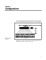
Страница 20: ... Typical Hub Configuration Ethernet Transceiver Coaxial Ethernet AUI Cable 100 Meters UTP Cable wired Pin to Pin 10BASE T Transceiver Workstations DTEs 10BASE T Transceiver 10BASE T Transceiver 10BASE T Transceiver AUI PORT 1 10 BASE T PORTS LINK TEST PORTS POWER 4 3 2 5 8 7 6 9 12 11 10 X X X X X X X X X X X X 1 3 5 9 7 11 2 4 6 10 8 12 10BASE T Transceiver 10BASE T Transceiver 10BASE T Transceiv...

Страница 21: ...7 11 2 4 6 10 8 12 AUI PORT 1 10 BASE T PORTS LINK TEST PORTS POWER 4 3 2 5 8 7 6 9 12 11 10 X X X X X X X X X X X X 1 3 5 9 7 11 2 4 6 10 8 12 AUI PORT 1 10 BASE T PORTS LINK TEST PORTS POWER 4 3 2 5 8 7 6 9 12 11 10 X X X X X X X X X X X X 1 3 5 9 7 11 2 4 6 10 8 12 UTP Link Segment UTP Link Segment Figure 7 Hubs on a Backbone 12 UTP Segments 12 UTP Segments 12 UTP Segments AUI PORT 1 10 BASE T ...

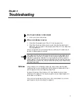
Страница 22: ...net wiring costs UTP wiring is installed in most buildings for telephone systems Care must be taken to ensure the UTP wiring used for 10BASE T is able to carry the high Ethernet data rates before a 10BASE T network solution is implemented Unlike coaxial Ethernet 10BASE2 and 10BASE5 10BASE T UTP is point to point wiring Typically one end is connected to an Ethernet 10BASE T Network Interface Contro...

Страница 23: ... of a thick coax segment is 2165 ns Propagation delay of thick Ethernet coax is calculated at 4 33 ns meter Both ends of the segment must be terminated with a 50 Ω termination with a power rating of 0 5 watts or greater Earth grounding of the segment shield must take place only at one point on the cable Propagation Propagation delay is the time it takes a signal to travel from the input of a syste...

Страница 24: ...nnection This concentration of UTP ports is later broken out for connection to a punch down block inside a building s wiring closet 50 pin Telco connections provide a very clean uncluttered interface to the building s wiring ATTACHMENT UNIT INTERFACE AUI This is the cable connection from a MAU transceiver to a DTE typically a workstation consisting of a 15 conductor twisted pair cable of 50 meters...

Страница 25: ...yer to indicate that multiple stations are contending for access to the transmission medium COMPATIBILITY INTERFACE The MDI coaxial cable interface and the AUI branch cable interface the two points at which hardware compatibility is defined to allow connection of independently designed and manufactured components to the baseband transmission system CROSS OVER Wiring is used when connecting a 10BAS...

Страница 26: ...or 10 Megabit data rates In these circumstances it is recommended that the wiring is tested with a 10BASE T signal wire tester IMPEDANCE An electrical characteristic of a circuit dealing with the combination of the AC and DC resistance and the appearance of that resistance to attached circuits JABBER LOCK UP The MAU s ability to automatically inhibit the transmit data from reaching the medium if t...

Страница 27: ...des a convenient way for the installer or network manager to connect the hub 10BASE T ports into the desired building locations PHYSICAL MEDIUM ATTACHMENT PMA The portion of the MAU that contains the functional circuitry PHYSICAL SIGNALING PLS That portion of the physical layer contained within the DTE that provides the logical and functional coupling between MAU and data link layers POLARITY CORR...

Страница 28: ...This connector is a 10BASE T standard for connecting UTP cabling They are inexpensive and easy to install onto UTP cable SIGNAL QUALITY ERROR SQE Also referred to as Collision or Collision Presence This occurs when two devices attempt to transmit at the same time which is an illegal condition SQE TEST Commonly referred to as Heartbeat is a special 802 3 signal sent by the MAU to the DTE to test th...

Отзывы: