Chapter 2: Installation
42
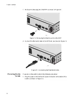
1. Remove the dust plug from the SFP, as shown in Figure 12.
Figure 12. Removing the Dust Cover from the SFP
2. Connect the fiber optic cable to the SFP port, as shown in Figure 13.
Figure 13. Connecting the Fiber Optic Cable
Powering On the
Switch
To power on the switch, perform the following procedure:
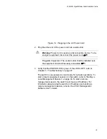
1. Plug the power cord into the AC power connector on the back of the
switch, as shown in Figure 14.
803
799
Содержание AT-9000/24
Страница 1: ...613 000239 Rev A Layer 2 Gigabit Ethernet Switch AT 9000 24 Installation Guide...
Страница 6: ...Contents 6 Appendix B Translated Safety Statements 53...
Страница 8: ...Figures 8...
Страница 10: ...Tables 10...
Страница 28: ...Chapter 1 Overview 28...
Страница 46: ...Chapter 2 Installation 46...
Страница 48: ...Chapter 3 Troubleshooting 48...
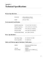
Страница 52: ...Appendix A Technical Specifications 52...
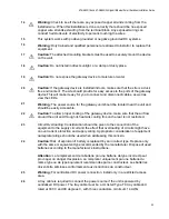
Страница 74: ...Appendix B Translated Safety Statements 74 1 1 2 3 LAN 4 5 6 I 7 8 9 40 C 10 11 15 LAN OFF 12...
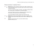
Страница 77: ...AT GA950 16 and AT GA950 24 Gigabit Ethernet Smart Switches Installation Guide 77 41 42 TEL PSTN 43 26 AWG...
Страница 78: ...Appendix B Translated Safety Statements 78...


