


Chapter 1: Overview
20
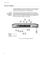
LEDs
The LEDs on the front panel display the system and port status
information. Each port has two LEDs as shown in Figure 3.
Figure 3. AT-9000/24 System and Port LEDs
Table 2 describes the AT-9000/24 system LEDs.
Table 3 describes the LEDs for the 10/100/1000Base-T ports.
Table 2. System LEDs
LED
State
Description
POWER
Off
The switch is not receiving power.
On
The switch is receiving power.
Table 3. 10/100/1000Base-T Port LEDs
LED
State
Description
SPEED
On
The port is operating at 1000 Mbps.
Off
The port is operating at 10/100 Mbps or no
link is established.
LINK/ACT Off
The port has not established a link with an
end node.
Blinking
Green
The port is transmitting or receiving data.
Green
A valid link has been established on the port.
795
AT-9000/24
24 Port Gigabit Ethernet Switch
1
3
5
7
9
11
13
15
17
19 21R 23R
2
4
6
8
10
12
14
16
18
20 22R 24R
POWER
21
22
23
24
SFP
LINK
ACT
1000
10/100
PORT ACTIVITY
Содержание AT-9000/24
Страница 1: ...613 000239 Rev A Layer 2 Gigabit Ethernet Switch AT 9000 24 Installation Guide...
Страница 6: ...Contents 6 Appendix B Translated Safety Statements 53...
Страница 8: ...Figures 8...
Страница 10: ...Tables 10...
Страница 28: ...Chapter 1 Overview 28...
Страница 46: ...Chapter 2 Installation 46...
Страница 48: ...Chapter 3 Troubleshooting 48...
Страница 52: ...Appendix A Technical Specifications 52...
Страница 74: ...Appendix B Translated Safety Statements 74 1 1 2 3 LAN 4 5 6 I 7 8 9 40 C 10 11 15 LAN OFF 12...
Страница 77: ...AT GA950 16 and AT GA950 24 Gigabit Ethernet Smart Switches Installation Guide 77 41 42 TEL PSTN 43 26 AWG...
Страница 78: ...Appendix B Translated Safety Statements 78...


