Section 4
4 - 5
CBR
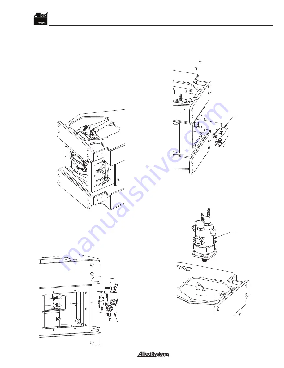
Manifold
Control
Manifold
Vane
Motor
Motor Removal
Winches with optional DRAG-BRAKE
1. Drain oil from gear compartment or remove breather
and install pipe plug.
Note: Tag or label all hydraulic hose ends and tubes
to aid during reinstallation. Also note the location of
any hose clamps.
2. Remove winch from tractor.
3. Position winch on its left side and block securely.
4. Remove right-hand side cover, front cover, and top
cover.
5. Remove all hoses, wiring harnesses, and tube as-
semblies. Tag hose ends and ports for reassembly.
Use caps to prevent contamination of open ports
and hose ends.
6. Remove the counterbalance relief (CBR) manifold.
7. Remove the control manifold.
8. Remove the four fasteners in the motor fl ange. Then
you can remove the motor, using a suitable lifting
strap or device. Note motor orientation to aid in re-
installation.
Содержание H5C Series
Страница 8: ...vi Notes...
Страница 48: ...General 1 40 Notes...
Страница 50: ...Section 1 1 42 H5CT K371 2 SPEED KOM D51 24 Figure 1 33 H5C Hydraulic Electrical Schematic Komatsu D51 24 K371...
Страница 59: ...Troubleshooting 2 6 Notes...
Страница 77: ...Service 3 18 Notes...
Страница 86: ...Section 4 4 9 Intentionally Blank...
Страница 104: ...Section 4 4 27 Intentionally Blank...
Страница 108: ......


