Allied Air 030-B12 Скачать руководство пользователя страница 17

507867-02

Page 17 of 54

Issue 2128

6.  After  determining  that  each  appliance  connected  to 

the common venting system is venting properly, (step 

3)  return  all  doors,  windows,  exhaust  fans,  fireplace 

dampers,  and  any  other  gas  burning  appliances  to 

their previous mode of operation.

7.  If  a  venting  problem  is  found  during  any  of  the 

preceding tests, the common venting system must be 

modified to correct the problems.

Resize the common venting system to the minimum vent 

pipe  size  determined  by  using  the  appropriate  tables  in 

Appendix  G.  (These  are  in  the  current  standards  of  the 

National Fuel Gas Code ANSI Z223.1.
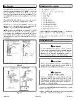
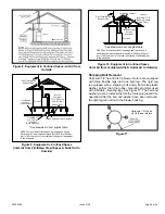
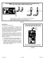
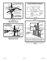
Exhaust Piping

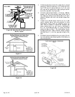
See Figure 25 and Figure 26
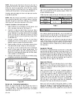
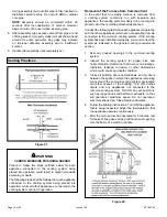
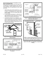
1.  In areas where piping penetrates joist or interior walls, 

hole must be large enough to allow clearance on all 

sides of pipe through center of hole using a hanger.

2.  When  furnace  is  installed  in  a  residence  where  unit 

is  shut  down  for  an  extended  period  of  time,  such 

as  a  vacation  home,  make  provisions  for  draining 

condensate collection from trap and lines.

3.  Route  piping  to  outside  of  structure.  Continue  with 

installation  following  instructions  given  in  piping 

termination section.

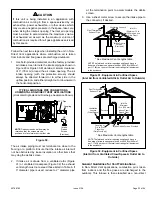
Do  not  discharge  exhaust  into  an  existing  stack  or 

stack that also serves another gas appliance. If vertical 

discharge through an existing unused stack is required, 

insert PVC pipe inside the stack until the end is even 

with the top or outlet end of the metal stack.

 CAUTION

The exhaust vent pipe operates under positive pressure 

and must be completely sealed to prevent leakage of 

combustion products into the living space.

 CAUTION

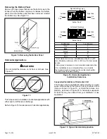
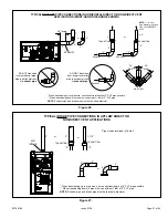
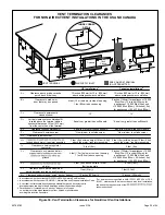
Vent Piping Guidelines

This gas furnace can be installed as either a Non-Direct 

Vent or a Direct Vent gas central furnace.

NOTE: 

In non-Direct Vent installations, combustion air is 

taken from indoors and flue gases are discharged outdoors. 

In Direct Vent installations, combustion air is taken from 

outdoors and flue gases are discharged outdoors.

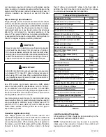
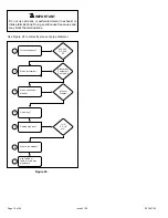
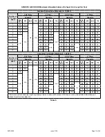
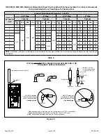
Intake  and  exhaust  pipe  sizing  -  Size  pipe  according  to 

Table  4  and  Table  5  through  Table  6.  Table  4  lists  the 

minimum vent pipe lengths permitted. Table 5 and Table 

list the maximum pipe lengths permitted for A93UH1E & 

92G1UHE.

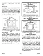
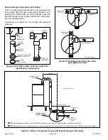
Regardless of the diameter of pipe used, the standard roof 

and wall terminations described in section Exhaust Piping 

Terminations  should  be  used.  Exhaust  vent  termination 

pipe is sized to optimize the velocity of the exhaust gas as 

it exits the termination. Refer to Table 8.

In  some  applications  which  permit  the  use  of  several 

different sizes of vent pipe, a combination vent pipe may 

be used. Contact Allied Air Technical Service for assistance 

in sizing vent pipe in these applications.
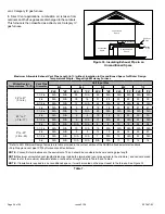
Figure 23. 

NOTE: 

It  is  acceptable  to  use  any  pipe  size  which  fits 

within the guidelines allowed in Table 5 and Table 6.

NOTE: 

The  exhaust  collar  on  all  models  is  sized  to 

accommodate  2”  Schedule  40  vent  pipe.  In  horizontal 

applications, transition to exhaust pipe larger than 2” must 

be made in vertical runs of the pipe. A 2” elbow must be 

added  before  the  pipe  is  transitioned  to  any  size  larger 

than  2”.  This  elbow  must  be  added  to  the  elbow  count 

used  to  determine  acceptable  vent  lengths.  Contact  the 

Application  Department  for  more  information  concerning 

sizing of vent systems which include multiple pipe sizes. 
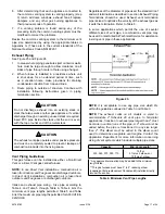
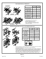
Capacity

Min. Vent Length*

030, 045, 070, 090, 110

15 ft. or


5 ft plus 2 elbows or


10 ft plus 1 elbow

* Any approved termination may be added to the minimum 

length listed.
** This gas furnace must have 3” to 2” reducing elbow 

(supplied or field replacement Canadian kit) installed directly 

into unit flue collar.

Table 4. Minimum Vent Pipe Lengths

Содержание 030-B12

Страница 1: ...amage personal injury or loss of life Installation and service must be performed by a licensed professional installer or equivalent service agency or the gas supplier WARNING As with any mechanical eq...

Страница 2: ...Issue 2128 Unit Dimensions FRONT VIEW SIDE VIEW Capacity A B C D in mm in mm in mm in mm 030 B12 045 B12 070 B12 17 1 2 446 16 3 8 416 16 406 1 5 8 194 090 C12 090 C16 110 C16 110 C20 21 533 19 7 8 50...

Страница 3: ...lve Combustion Air Inducer Blower Access Door Combustion Air Pressure Prove Switch Cold End Header Box Control Box includes integrated ignition control transformer and interlock switch Blower Assembly...

Страница 4: ...Snap bushing 1 Snap Plug 1 Wire tie 1 Condensate trap 1 Condensate trap cap 1 Condensate trap clamp 1 2 diameter debris screen 1 3 4 Threaded street elbow Check equipment for shipping damage If you fi...

Страница 5: ...dards NOTE Furnace must be adjusted to obtain a temperature rise within the range specified on the unit nameplate Failure to do so may cause erratic limit operation and premature heat exchanger failur...

Страница 6: ...ALL OF THE FOLLOWING CRITERIA ARE MET a Furnace must be in its final location The vent system must be permanently installed per these installation instructions b Furnace must be installed as a two pi...

Страница 7: ...inated atmosphere Meet all combustion and ventilation air requirements as well as all local codes CAUTION In the absence of local codes concerning air for combustion and ventilation use the guidelines...

Страница 8: ...a minimum free area of 1 square inch per 4 000 Btu 645 mm per 59 kW per hour of total input rating of all equipment in the enclosure see Figure 6 and Figure 7 It is also permissible to bring in air fo...

Страница 9: ...let Air to Outside Ventilation Louvers Inlet Air Minimum 12 in 305mm above Attic Floor Roof Terminated Exhaust Pipe Furnace Intake Debris Screen Provided See Maximum Vent Lengths table NOTE The inlet...

Страница 10: ...late Also consider gas supply connections electrical supply vent connection and installation and service clearances 24 inches 610 mm at unit front The unit must be level Do not connect the return air...

Страница 11: ...th optional RAB Return Air Base Bottom return air Return air from both sides Bottom and one side return air FRONT VIEW SIDE VIEW 1 Unit side return air Opening 3 1 4 83 1 23 584 Overall Maximum 584 23...

Страница 12: ...Left End Air Flow Air Flow Left Hand Discharge Bottom floor Right End Left End Air Flow Air Flow Top Plenum 1 in 25 mm Front 0 Back 0 Sides 0 Vent 0 Floor 0 Front clearance in alcove installation mus...

Страница 13: ...lters This unit is not equipped with a filter or rack Afield provided filter is required for the unit to operate properly Table 1 list recommended filter sizes A filter must be in place whenever the f...

Страница 14: ...vent pipe hangers Uniformly apply a liberal coat of PVC primer for PVC or use a clean dry cloth for ABS to clean inside socket surface of fitting and male end of pipe to depth of fitting socket Canad...

Страница 15: ...et surface and end of pipe are wet with cement forcefully insert end of pipe into socket until it bottoms out Turn PVC pipe 1 4 turn Capacity VENT PIPE DIA in STANDARD CONCENTRIC Outdoor Exhaust Accel...

Страница 16: ...blockage restriction leakage corrosion or other deficiencies which could cause an unsafe condition 3 Close all building doors and windows and all doors between the space in which the appliances remain...

Страница 17: ...urnace NOTE In non Direct Vent installations combustion air is taken from indoors and flue gases are discharged outdoors In Direct Vent installations combustion air is taken from outdoors and flue gas...

Страница 18: ...ck the terminations IMPORTANT Use Figure 24 to correctly size vent pipe diameter 030 045 070 090 110 Standard or Concentric See Table 3 Intake or Exhaust 1 1 2 2 2 1 2 or 3 Furnace capacity 1 Which te...

Страница 19: ...26 n a 75 60 28 n a 97 97 78 78 9 36 21 70 55 23 92 92 73 73 10 31 16 65 50 18 87 87 68 68 Concentric Termination Elevation 0 10 000 ft Number of 90 Elbows Used 1 1 2 Pipe 2 Pipe 2 1 2 Pipe 3 Pipe Cap...

Страница 20: ...65 50 18 82 82 63 63 8 31 16 60 45 13 77 77 58 58 9 26 11 55 40 8 72 72 53 53 NOTE Additional vent pipe and elbows used to terminate the vent pipe outside the structure must be included in the total...

Страница 21: ...n horizontal runs of exhaust pipe When transitioning up in pipe size use the shortest length of 2 PVC pipe possible When transitioning down in pipe size use at least 1 foot of 2 PVC pipe NOTE Exhaust...

Страница 22: ...and guidelines listed in Combustion Dilution and Ventilation Air section must be followed Follow the next two steps when installing the unit in Direct Vent applications where combustion air is taken...

Страница 23: ...take air inlet will not be obstructed by loose insulation or other items that may clog the debris screen 2 If intake air is drawn from a ventilated attic Figure 31 or ventilated crawlspace Figure 32 t...

Страница 24: ...N A 3 in N A N A 9 9 18 18 35 35 47 47 20 to 1 7 to 17 1 1 2 in N A N A 15 N A 20 N A N A N A N A N A 2 in N A N A 9 8 18 16 32 29 30 30 2 1 2 in N A N A 5 N A 13 N A 24 N A 34 N A 3 in N A N A N A N...

Страница 25: ...arance under veranda porch deck or balcony 12 Equal to or greater than soffit depth 3 feet 9m 12 3 feet 9m within a height 15 feet 4 5m above the meter regulator assembly 3 feet 9m 6 inches 152mm for...

Страница 26: ...s 152mm for appliances 10 000 pliances 10 000 Btuh 3kw and 50 000 pliances 50 000 Btuh 15kw 6 inches 152mm for appliances 10 000 Btuh 3kw 12 inches 305mm for appliances 10 000 Btuh 3kw and 100 000 Btu...

Страница 27: ...tallation codes the minimum allowed distance between the combustion air intake inlet and the exhaust outlet of other appliances shall not be less than 12 inches 305 mm IMPORTANT Details of Intake and...

Страница 28: ...44 6 On field supplied terminations a minimum distance between the end of the exhaust pipe and the end of the intake pipe without a termination elbow is 8 and a minimum distance of 6 with a terminatio...

Страница 29: ...045 and 070 models EXHAUST VENT Figure 41 Direct Vent Concentric Wall Termination 71M80 69M29 or 60L46 US 44W92 or 44W93 Canada Figure 42 STRAIGHT CUT OR ANGLE CUT IN DIRECTION OF ROOF SLOPE EXHAUST V...

Страница 30: ...d be connected to the 2 or 3 PVC flue pipe as shown in the illustration Do not use an accelerator in applications that include an exhaust termination tee The accelerator is not required 2 As required...

Страница 31: ...CUMULATION SIZE PER EXHAUST PIPE TERMINATION SIZE REDUCTION TABLE Figure 46 Non Direct Vent Field Supplied Wall Termination SIZE TERMINATION PER EXHAUST PIPE TERMINATION SIZE REDUCTION TABLE FIELD PRO...

Страница 32: ...ermination Drain Trap assembled Figure 49 Kit 51W18 USA 15Z70 Canada Parts Identification and Assembly Exhaust from Furnace To Termination Exhaust from Furnace To Termination Kit 51W18 is shown Figure...

Страница 33: ...n tape or appropriate pipe dope 3 Install the cap over the clean out opening at the base of the trap Secure with clamp See Figure 58 4 Install drain trap using appropriate PVC fittings glue all joints...

Страница 34: ...iping from furnace must slope down a minimum of 1 4 per ft toward trap Figure 55 Evaporator Coil Using a Separate Drain Figure 56 Evaporator Coil Using a Common Drain Piping from furnace must slope do...

Страница 35: ...507867 02 Page 35 of 54 Issue 2128 Figure 58 Trap Drain Assembly Using 1 2 PVC or 3 4 PVC...

Страница 36: ...ide of unit See Figure 61 and Figure 62 4 Piping should be sloped 1 4 per 15 feet 6 mm per 5 6 m upward toward the gas meter from the furnace The piping must be supported at proper intervals every 8 t...

Страница 37: ...ted WARNING Figure 61 Gas Piping Upflow Applications NOTE BLACK IRON PIPE ONLY TO BE ROUTED INSIDE OF CABINET FIELD PROVIDED AND INSTALLED GROUND JOINT UNION DRIP LEG MANUAL MAIN SHUT OFF VALVE Upflow...

Страница 38: ...16 42 530 15 01 490 13 87 460 13 03 430 12 18 400 11 33 1 1 2 38 1 1 610 40 894 2100 59 46 460 41 34 1180 33 41 990 28 03 900 25 48 810 22 94 750 21 24 690 19 54 650 18 41 620 17 56 2 50 8 2 067 52 50...

Страница 39: ...wer for service Complete the wiring connections to the equipment Use the provided unit wiring diagram and the field wiring diagram shown in Figure 66 Use 18 gauge wire or larger that is suitable for C...

Страница 40: ...the heating speed 3 When there is a cooling demand the indoor blower will run on the cooling speed Generator Use Voltage Requirements The furnace requires 120 volts 10 Range 108 volts to 132 volts Th...

Страница 41: ...507867 02 Page 41 of 54 Issue 2128 Figure 67 Typical Wiring Diagram...

Страница 42: ...ARNING Danger of explosion Can cause injury or product or property damage Should the gas supply fail to shut off or if overheating occurs shut off the gas valve to the furnace before shutting off the...

Страница 43: ...r to the unit 11 Set the thermostat to desired setting NOTE When unit is initially started steps 1 through 11 may need to be repeated to purge air from gas line 12 If the appliance will not operate fo...

Страница 44: ...bilize observe the flame Flame should be stable and should not lift from burner Natural gas should burn blue 4 After allowing unit to stabilize for 5 minutes record manifold pressure and compare to va...

Страница 45: ...s installation of a gas valve regulator spring which is provided with the gas conversion Kit LP Kits include low line pressure switch Table 13 Burner Orifice Conversion Kits at Varying Altitudes Capac...

Страница 46: ...d and other spaces of the building 4 Close fireplace dampers 5 Turn on clothes dryers and any appliances not connected to the venting system Turn on any exhaust fans such as range hoods and bathroom e...

Страница 47: ...ess panel in place Motor Nameplate__________Actual__________ Blower Speeds Follow the steps below to change the blower speeds 1 Turn off electrical power to furnace 2 Remove blower access panel 3 Disc...

Страница 48: ...90 348 1270 271 1135 199 885 109 735 71 0 20 1355 349 1230 280 1100 207 850 119 680 81 0 30 1330 368 1205 291 1060 220 795 126 625 84 0 40 1295 378 1180 298 1025 226 755 134 570 91 0 50 1265 386 1140...

Страница 49: ...06 1275 173 1160 135 0 20 1655 392 1460 273 1315 219 1230 185 1110 142 0 30 1615 408 1410 282 1290 225 1195 192 1065 151 0 40 1595 416 1365 295 1245 236 1155 203 1010 160 0 50 1560 429 1335 308 1200 2...

Страница 50: ...33 1880 441 1715 353 1605 288 1435 210 2135 614 1885 421 1705 342 1595 280 1415 207 0 20 2085 648 1830 455 1665 362 1560 298 1360 220 2085 628 1830 437 1670 351 1545 293 1370 218 0 30 2040 663 1795 46...

Страница 51: ...intake pipes and all connections for tightness and to make sure there is no blockage NOTE After any heavy snow ice or frozen fog event the furnace vent pipes may become restricted Always check the ven...

Страница 52: ...ating correctly 19 Replace heating compartment access panel Table 17 Control Diagnostic Codes Integrated Control LED Codes Red LED Flash Code2 Diagnostic Codes Status of Furnace LED Off No power to co...

Страница 53: ...s Problems detected during the inspection may make it necessary to temporarily shut down the furnace until the items can be repaired or replaced Instruct the homeowners to pay attention to their furna...

Страница 54: ...height of eight 8 feet above grade directly in line with the exhaust vent terminal for the horizontally vented gas fueled heating appliance or equipment The sign shall read in print size no less than...

Отзывы: