


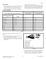


4. Crimp a ring terminal to the protection conductor so it stays
fixed to the PE terminal.
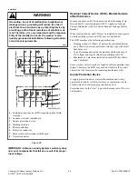
5. Connect the supply cable conductors to the incoming termi-
nals (main switch [1]), marked with L1/U, (L2/V), (L3/W),
(N) and the terminal marked with PE. Refer to
or
.
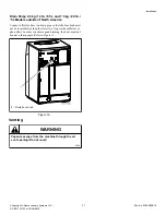
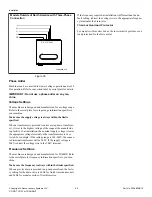
6. Provide a sag in the cable, in front of the strain relief. This
will prevent condensed water from dripping into the machine.
Refer to
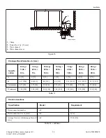
Models outside of North America
CHM2488N_SVG
7
6
5
4
3
2
1
1.
Main switch
2.
Strain relief
3.
Sag of inlet cable
4.
N
5.
W
6.
V
7.
U
Figure 30
North American Models
1.
Main switch
2.
Strain relief
3.
Sag of inlet cable
4.
L3
5.
L2
6.
L1
Figure 31
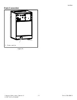
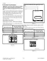
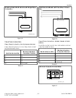
Machine Protective Earth Connection and
Equipotential Bonding
If there are other washers or appliances with exposed conductive
parts, which can touch simultaneously, make sure to make equi-
potential bonding between all these appliances. The external pro-
tective terminal for this purpose is located on the rear panel of the
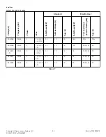
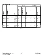
machine frame. The minimum protection conductor's cross sec-
tion depends on the supply cable cross section (refer to
). However, for the protection purposes, with the supply cable
cross section of a min. 4 mm
2
, select a larger conductor section,
i.e., 6 mm
2
.
Installation
©
Copyright, Alliance Laundry Systems LLC -
DO NOT COPY or TRANSMIT
46
Part No. D1598ENR10
Содержание UY105 PRO
Страница 2: ......


