


Machine Installation
Install the machine close to a floor drain or open drain.
Elevated Base Frame Installation with
Existing Floor (Base Frame Supplied
by Manufacturer)
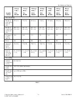
The elevated base frame structure must be able to withstand the
static and dynamic loads of the machine floor (refer to
), and it must allow the machine to be seated in a
perfectly level manner.
IMPORTANT: Floor or plinth under machine must be
level, stable, and straight to prevent the frame from
twisting. The manufacturer is not responsible for any
defomation of the frame caused by not fulfilling these
conditions.
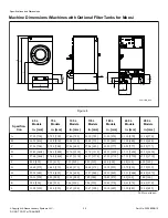
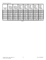
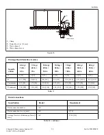
1. Drill four holes for anchoring bolts (6) into the floor. Refer to
. Refer to dimensions E and K in
and
for spacing of the holes. The diameter of the openings in the
base frame is .49" [12 mm].
2. Install mechanical or chemical anchoring bolts into the holes
drilled in the floor.
NOTE: The anchoring bolts are not included in the
machine supply.
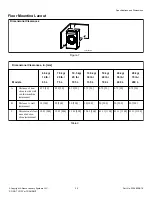
3. Place the base frame on the anchoring bolts so that the four 35
mm openings are upwards and the BACK label is at the back
of the machine.
4. Make sure the base frame is level.
5. Place the washers (4) and nuts (5) on the anchoring bolts and
tighen to a torque of 80 Nm. Refer to
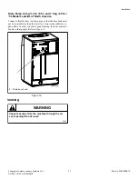
6. Remove the transport packaging from the machine.
7. Remove the front and rear panels from the machine.
8. Remove the bolts fastening the machine to the pallet, but DO
NOT mount the adjustable feet from the machine packaging
on the bottom frame of the machine.
9. Install the machine on the anchored base frame.
NOTE: When removing the machine from the pallet,
do not put the rear corner of the machine on the
floor first. This can cause damage to the side panel
of the machine or frame.
10. Make sure the machine is level.
11. Fasten the machine to the base frame using bolts M10x35 (7),
washers M10 (9), and spring washers M10 (8). Refer to
. Tighten to a torque of 50 Nm.
12. Remove the shipping brace. Refer to
13. Re-install the front and rear panels on the machine.
9
8
7
4
5
6
1
2
3
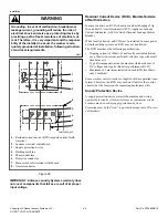
CFS672N_SVG
1.
Floor
2.
Base frame
3.
Machine frame
4.
Anchoring bolt washer
5.
Anchoring bolt nut
6.
Anchoring bolt
7.
Bolt M10x35
8.
Spring washer M10
9.
Washer M10
Figure 10
Installation
©
Copyright, Alliance Laundry Systems LLC -
DO NOT COPY or TRANSMIT
29
Part No. D1598ENR10
Содержание UY105 PRO
Страница 2: ......


