068521
Page 23
SECTION 2
ASSEMBLY
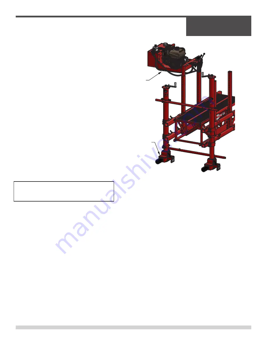
Installing Power Wheel Option:
1. Place Power Wheel Power Unit
on Work Bridge as shown in
figure.
2. Attach Power Unit with 1/2”-13
x 3-1/2” bolt (045855 x 4) and
Nut (011238 x 4)
3. Remove the original Non-Pow-
ered Wheels from the machine
and replace with the Power
Wheels as shown.
4. Attach the Hydraulic hoses as
follows:
• Drive Wheels - Blue/Red
• Idle Wheels - Green/White
Assembly Instructions
Power Wheel
Power Unit
Power Wheel
Note:
Pictures are for reference only.
WB1824 shown
Содержание WB2434
Страница 10: ...SECTION 1 SAFETY 068521 Page 10 SECTION 1 SAFETY ...
Страница 20: ...SECTION 2 ASSEMBLY 068521 Page 20 SECTION 2 ASSEMBLY ...
Страница 25: ...068521 Page 25 SECTION 2 ASSEMBLY Assembly Instructions ...
Страница 26: ...SECTION 3 PARTS 068521 Page 26 SECTION 3 PARTS ...
Страница 43: ...068521 Page 43 SECTION 3 PARTS PAGE LEFT BLANK INTENTIONALLY ...
Страница 44: ...SECTION 3 PARTS 068521 Page 44 5 2 1 4 3 Decals WB2434 ...


