3.3 Lift Lever Adjustment Procedure
Damage to and/or replacement of a trowel arm can change the adjustment of the lift
lever. This can unbalance the trowel arms and cause the riding trowel to wobble
during operation. To operate smoothly the lift lever on all trowel arms must be
adjusted the same to ensure that the riding trowel is balanced correctly.
Adjusting the trowel arms is accomplished by using the optional trowel arm alignment
jig (Part #: 016863)
. The service manual that is included with the alignment jig
describes in detail the steps to preform this procedure and to check the flatness and
straightness of the trowel arms.
The steps below describe the general procedure to remove the trowel arms to be aligned.
1. Block up pressure plate
[A]
using a wooden block.
2. Remove stabilizer ring from spider assembly (only on available models).
3. Remove blades from trowel arms.
4. Loosen hex head cap screw
[B]
and remove it and the external star washer from the spider boss.
5. Remove trowel arms from spider boss with lift levers in place.
6. Clean flats on trowel arm before placing it in the trowel arm jig (Part #: 016863).
7. Preform the alignment procedures as outlined in the alignment jig service manual (Part #: 047427).
8. Re-attach trowel arm to spider boss and blades to trowel arms.
9. Tighten down hex head cap screw to secure trowel arm in place.
10. Reattach stabilizer ring (only on available models).
Lift Lever Adjustment
Make sure there is NO pitch in the blades
before attempting to remove a trowel arm.
SECTION 3
SERVICE
064634
Page 42
Содержание PRO WALK-BEHIND
Страница 11: ...Machine Dimensional Specifications 064634 Page 11 GENERAL INFORMATION ...
Страница 16: ...Notes 064634 Page 16 GENERAL INFORMATION ...
Страница 17: ...SECTION 1 SAFETY SECTION 1 SAFETY 064634 Page 17 ...
Страница 18: ...State Regulations SECTION 1 SAFETY 064634 Page 18 ...
Страница 19: ...Federal Regulations SECTION 1 SAFETY 064634 Page 19 ...
Страница 28: ...Notes SECTION 1 SAFETY 064634 Page 28 ...
Страница 29: ...SECTION 2 OPERATIONS SECTION 2 OPERATIONS 064634 Page 29 ...
Страница 35: ...2 1 3 4 5 6 7 8 9 10 11 12 13 14 15 Trowel Controls SECTION 2 OPERATIONS 064634 Page 35 ...
Страница 38: ...Notes SECTION 2 OPERATIONS 064634 Page 38 ...
Страница 39: ...SECTION 3 SERVICE SECTION 3 SERVICE 064634 Page 39 ...
Страница 46: ... SECTION 4 PARTS SECTION 4 PARTS 064634 Page 46 ...
Страница 47: ...PAGE LEFT BLANK INTENTIONALLY SECTION 4 PARTS 064634 Page 47 ...
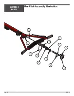
Страница 52: ...2 8 3 4 5 7 6 11 10 9 1 12 Fine Pitch Assembly Illustration SECTION 4 PARTS 064634 Page 52 ...
Страница 99: ...PAGE LEFT BLANK INTENTIONALLY SECTION 4 PARTS 064634 Page 99 ...
Страница 105: ......


