background image

SECTION 2

OPERATIONS

SECTION 2

OPERATIONS

064634

Page 29

Содержание PRO WALK-BEHIND

Страница 1: ...OPERATIONS PARTS MANUAL Manual Part 064634 Revision C Language English Original Instructions W A L K B E H I N D T R O W E L S PRO WALK BEHIND ...

Страница 2: ... ADJ HANDLE RAPID Copyright 2020 Allen Engineering Corporation All rights reserved All information specifications and illustrations in this manual are subject to change without notice and are based on the latest information at the time of publication No part of this manual may be reproduced or transmitted in any form or by any means electronics or mechanical for any purpose without the express wri...

Страница 3: ...irs made to the product without the written approval of Allen Allen specifically excludes from warranty any damage to any trowels resulting from an impact to the rotors 7 Impact damage to gear boxes is not covered under the Allen warranty and is deemed customer abuse 8 Allen will pay shop labor on warranty items at the Allen Shop Labor Rate in existence on the date of the warranty claim An Allen l...

Страница 4: ...nformity 16 1 0 Safety 17 State Regulations 18 Federal Regulations 19 General Safety Precautions 20 Spark Arrestor Notice 21 General Safety 22 Engine Safety 25 Transportation Safety 26 Safety And Operation Labels 27 2 0 Operations 29 Introduction 30 Start Up Procedures 32 Engine Controls 33 Trowel Controls 34 Operating Instructions 36 3 0 Service 39 Periodic Maintenance 40 Trowel Gearbox 41 Lift L...

Страница 5: ...der 446 64 Spider 446SD 65 Power Unit 430 Edging 66 Power Unit 436 Edging 70 Power Unit 436 74 Kit 436 with Kohler Engine 78 Power Unit 436 TC 80 Power Unit 446 82 Power Unit 446SD 86 Kit 446 with Kohler Engine 90 Power Unit 446SD TC 92 Safety Switch Assembly 96 Universal Walk Behind Hardware Kit 97 Filter Kits Replacement 98 Decals PRO436 100 Decals PRO436E 101 Decals PRO446 102 Decals PRO446TC 1...

Страница 6: ...tions Complete any warranty requirements as specified by the engine manufacturer in their instructions found inside the manual box located on the back of the riding trowel operator s seat Your engine and clutch is not manufactured by Allen Engineering Corporation Inc and therefore is not covered under Allen Engineering Corporation Inc warranty Your engine manufacturer should be contacted if you wi...

Страница 7: ...ing and complete destination address 4 DO NOT return parts to AEC without receiving written authorization from AEC All authorized returns must be shipped pre paid 5 When placing an order please contact the AEC dealer nearest you ALL INFORMATION SPECIFICATIONS AND ILLUSTRATIONS IN THIS MANUAL ARE SUBJECT TO CHANGE WITHOUT NOTICE AND ARE BASED ON THE LATEST INFORMATION AT THE TIME OF PUBLICATION You...

Страница 8: ...r group of characters of the Model Number and Serial Number codes Serial Number The serial number found on the identification plate is a ten digit format The model number identifies your machine and will ensure that you receive the correct replacement parts 436 01 11 005 Production Sequence Model Number PRO 436 MODEL Year Mfd Month Mfd Series Model SERIES Model Number Serial Number Codes 064634 Pa...

Страница 9: ...f mainframe Refer to Figure 1 for serial number and model number location This plate should not be removed at any time Please record the information found on this plate below so it will be available should the identification plate become lost or damaged When ordering parts or requesting service information you will always be asked to specify the model and serial numbers of the machine FILL IN FOR ...

Страница 10: ...tor Speed RPM 110 135 Finish Blade Standard Gearbox Standard Duty STD Fixed Guard Rings Standard Fixed Seat Frame Standard Powered Retardant Spray System Standard Spray System Capacity gal L 6 23 Steering System Dual Levers Gearbox Rotation Standard Battery 12 Volt Safety Shutdown Switch Centrifugal Dead Man Fuel Capacity gal L 1 6 6 05 Run Time Approximate hr 2 5 Transmission Type Clutch Drive Be...

Страница 11: ...Machine Dimensional Specifications 064634 Page 11 GENERAL INFORMATION ...

Страница 12: ... System Digital CDI with variable ignition timing Starting System Recoil electric Governor System Centrifugal Mass Type Air cleaner Dual element Fuel Tank Capacity 5 6 U S qts 5 3 liters Fuel Unleaded 86 octane or higher Dry Weight 55 lb 25 kg Honda GX390 Engine Information 13 HP Engine Type Air cooled 4 stroke OHV Bore x Stroke 88 X 64 mm Displacement 389 cm3 Net Power Output 11 7 HP 8 7 kW 3 600...

Страница 13: ...cement 16 9 in3 277 cm3 Power Output 9 5 HP 7 1 kW Gross Torque 13 9 lb ft 18 8 Nm Compression Ratio 8 5 1 Oil Capacity 1 4 Qts 1 3 L Starting System Recoil Governor System Electronic Fuel Unleaded 87 octane or higher Dry Weight 61 7 lb 27 8 kg Length min 15 9 40 4 cm Width min 16 8 42 7 cm Height min 16 7 42 4 cm 064634 Page 13 GENERAL INFORMATION ...

Страница 14: ...the ride on trowel on curing concrete in a manner most often experienced in normal circum stances Values were obtained from all three axes of motion The values shown represent the maximum RMS value from these measurements Summary Data Of Sound And Vibration Testing for CE Marking Test Machine Engine Type Distant Sound Press Operator Ear SPL Sound Power Level Seat Vibration Overall Foot Vibration O...

Страница 15: ...ve The Technical Construction file is maintained at Allen Engineering Corporation 819 South 5th St Paragould AR 72450 Telephone 800 643 0095 Facsimile 800 643 0097 The authorized representative is ab lin pro Mr Thomas Voeler Femvägsskälet 3 421 50 Västra Frölunda Sweden Tel 4631694910 Mobile 46 706694923 Fax 4631298876 Email tv lin pro se Signature of Authorized Person s Typed name of Authorized P...

Страница 16: ...Notes 064634 Page 16 GENERAL INFORMATION ...

Страница 17: ...SECTION 1 SAFETY SECTION 1 SAFETY 064634 Page 17 ...

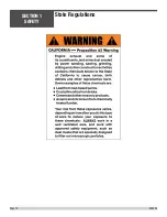
Страница 18: ...State Regulations SECTION 1 SAFETY 064634 Page 18 ...

Страница 19: ...Federal Regulations SECTION 1 SAFETY 064634 Page 19 ...

Страница 20: ...information EMERGENCY is used for the identification of safety equipment first aid or emergency egress locations NOTICE used to convey safety information on labels and signs CAUTION is indicative of a potentially hazardous situation which if not avoided may result in minor or moderate injury Potentially hazardous situations that could result in death or serious injury are indicated by the word WAR...

Страница 21: ...a device designed to prevent the discharge of spark or flames from the engine exhaust It is often required when operating equipment on forested land to prevent the risk of fires Consult the engine distributor or local authorities and make sure that you comply with regulations regarding spark arrestors Spark Arrestor Notice SECTION 1 SAFETY 064634 Page 21 ...

Страница 22: ...ols etc that would constitute a hazard while the equipment is in operation No one other than the operator is to be in the working area when the equipment is in operation DO NOT use the equipment for any purpose other than its intended purposes or applications This equipment should only be operated by trained and qualified personnel 18 years of age and older Whenever necessary replace nameplate ope...

Страница 23: ...g air NEVER operate this equipment in any enclosed or narrow area where free flow of the air is restricted If the air flow is restricted it will cause injury to people and property and serious damage to the equipment or engine NEVER operate the equipment in an explosive atmosphere or near combustible materials An explosion or fire could result causing severe bodily harm or even death ALWAYS keep c...

Страница 24: ...hands inside the guard rings while starting or operating this equipment ALWAYS keep the machine in proper running condition Fix damage to machine and replace any broken parts immediately ALWAYS store equipment properly when it is not being used Equipment should be stored in a clean dry location out of the reach of children and unauthorized personnel A safety manual for operating and maintenance pe...

Страница 25: ...ese parts to cool before servic ing equipment NEVER run engine without an air filter or with a dirty air filter Severe engine damage may occur Service air filter frequently to prevent engine malfunction NEVER tamper with the factory settings of the engine or engine governor Damage to the engine or equipment can result if operating in speed ranges above the maximum allowable ALWAYS use extreme caut...

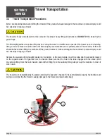
Страница 26: ...leared for such transport by the manufacturer Before lifting make sure that the lifting bales are not damaged NEVER hoist the trowel more than three feet off the ground with float pans attached Always make sure crane or lifting device has been properly secured to the lifting bales of the equipment DO NOT lift machine to unnecessary heights ALWAYS shutdown engine before transporting NEVER lift the ...

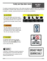
Страница 27: ... protection Also it highly rec ommends that the operator reads the manu al This label identifies the lift locations on the machine No other locations or features on the machine are to be used as lifting points This will cause damage to the machine For gasoline fueled machines this label identifies the tank used for GASOLINE fuel only in the machine NO OTHER type of fuel is to be used in this tank ...

Страница 28: ...Notes SECTION 1 SAFETY 064634 Page 28 ...

Страница 29: ...SECTION 2 OPERATIONS SECTION 2 OPERATIONS 064634 Page 29 ...

Страница 30: ...f improperly operated and serviced Follow operating instructions carefully If you have any questions about operating or servicing this equipment please contact your Allen Engineering Dealer or AEC Customer Service at 800 643 0095 or 870 236 7751 SECTION 2 OPERATIONS 064634 Page 30 ...

Страница 31: ...ions Power is transferred from the engine to the gearbox input shaft via a V belt pulley drive system The pulley engages using a clutch see the Parts Section Section 4 of this manual for a breakdown All Allen Engineering Walk behinds are equipped with a safety shutdown switch Operating time between fuel refills is approximately 2 1 2 to 3 hours with a rotor speeds of 110 to 135 RPM The walk behind...

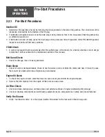
Страница 32: ...ed in the maintenance section of this manual Belt Guard Check 1 Check for damage lose or missing hardware Blade Check 1 Check for worn or damaged blades Check to see if a blade is worn out while the others look new If this is the case there could be a blade pitch issue Replace any worn blades Engine Oil Check 1 To check the engine oil level place the trowel on secure level ground with the engine s...

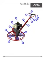
Страница 33: ...to stop the flow of fuel 6 Choke Lever Used in the starting of a cold engine or in cold weather conditions The choke enriches the fuel mixture 7 Air Cleaner Prevents dirt and other debris from entering the fuel system Remove wing nut on top of air filter can nister to gain access to filter element 8 Spark Plug Provides spark to the ignition system Set spark plug gap according to engine manufacture...

Страница 34: ...gine speed Returns engine to idle when released 9 Trowel Lifting Point The trowel is equipped with a lifting bail that can be used to safely lift and move the trowel 10 Main Tube When disassembling components inside the tube exercise caution 11 Guard Ring NEVER put hands or feet inside guard ring while the machine is running 12 Engine This trowel uses a Honda engine 13 Trowel Arm NEVER operate the...

Страница 35: ...2 1 3 4 5 6 7 8 9 10 11 12 13 14 15 Trowel Controls SECTION 2 OPERATIONS 064634 Page 35 ...

Страница 36: ...r the trowel gently lift up on or press down on the main trowel handle To move the machine to the operator s left lift up on the handle to move machine to the right push down on the handle 2 The best method for finishing concrete is to slowly walk backwards with the trowel guiding the trowel from side to side This will cover all footprints on wet concrete 3 Remember that if you let go of the trowe...

Страница 37: ... stages of the concrete When changing or setting pitch angle of trowel blades slow the machine down set the desired degree of pitch on the left side of the machine and then adjust the right side to match To increase the pitch turn the pitch control clockwise use the pitch indicator to adjust pitch equally on both right and left trowel blades Operating Instructions continued SECTION 2 OPERATIONS 06...

Страница 38: ...Notes SECTION 2 OPERATIONS 064634 Page 38 ...

Страница 39: ...SECTION 3 SERVICE SECTION 3 SERVICE 064634 Page 39 ...

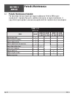
Страница 40: ...anual was supplied with the machine when it was shipped TABLE 3 1 1 CHECK LIST ITEM DAILY EVERY 20 HRS EVERY 50 HRS EVERY 100 HRS EVERY 300 HRS Grease towel arms ü Check oil level in gearbox ü Check engine oil level ü Check tighten external hardware ü Check drive belt for wear ü Check valve clearance ü Change engine oil ü Replace engine oil filter ü Replace spark plug ü Periodic Maintenance SECTIO...

Страница 41: ...dd oil tilt gearbox to the side and remove the fill plug Add oil through hole opening Replace fill plug after proper level has been achieved Fill so that there is oil 1 2 way in the sight glass Use Kluber GH 6 460 synthetic oil Trowel Gearbox GEARBOX 015202 FILL PLUG FILL PLUG LOCATION TOP COVER RELIEF VALVE SECTION 3 SERVICE 064634 Page 41 ...

Страница 42: ...neral procedure to remove the trowel arms to be aligned 1 Block up pressure plate A using a wooden block 2 Remove stabilizer ring from spider assembly only on available models 3 Remove blades from trowel arms 4 Loosen hex head cap screw B and remove it and the external star washer from the spider boss 5 Remove trowel arms from spider boss with lift levers in place 6 Clean flats on trowel arm befor...

Страница 43: ...Lift Lever Adjustment continued BLADE TROWEL ARM A PRESSURE PLATE LOCATION SPIDER BOSS B FASTENER HARDWARE REMOVAL SECTION 3 SERVICE 064634 Page 43 ...

Страница 44: ...ken when lifting the machine off the ground however Serious damage to the machine or personal injury could be caused by dropping a trowel Remove the auxiliary lifting tube B located on the bottom of the main handle Insert the tube into the socket C located on the opposite side of the gearbox from the handle Make sure that the hole in the tube engages with the socket With one person lifting from th...

Страница 45: ...plays lights switches wiring etc The electronic components may be damaged if water is sprayed on them Keep a perpendicular angle 90 when cleaning over a decal Holding nozzle of a pressure washer at an angle different from 90 may lift the decal from the machine Recommended using a safe cement dissolver BACK SET or similar to remove hardened concrete It is NOT recommended to use chemicals such as Mu...

Страница 46: ... SECTION 4 PARTS SECTION 4 PARTS 064634 Page 46 ...

Страница 47: ...PAGE LEFT BLANK INTENTIONALLY SECTION 4 PARTS 064634 Page 47 ...

Страница 48: ...d at the factory If set screw is removed or loosened for any reason re apply blue LOC TITE All grease fittings are capped with CAP PLUG GC 5 AEC PN 015692 to protect the fitting If cap becomes missing or damaged replace it as soon as possible Anti Seize is applied at the factory to all drive line coupling gear box main and counter shafts and pitch control threaded rod assemblies If these parts are...

Страница 49: ...number This manual contains an illustrated parts list for help in ordering replacement parts for your machine Follow the instructions below when ordering parts to insure prompt and accurate delivery 1 All orders for service parts include the serial number for the machine Shipment will be delayed if this information is not available 2 Include correct description and part number from the PARTS Secti...

Страница 50: ...lustration 21 3 3 4 4 22 23 14 10 16 IT 1 1 1 1 1 3 16 3 4 14 10 11 5 6 7 8 12 13 9 1 2 15 18 20 17 19 See page 52 for Fine Pitch Adjustment Assembly See page 88 for Safety Switch 8 Assembly SECTION 4 PARTS 064634 Page 50 ...

Страница 51: ...ROL LONG ASSEMBLY 1 11 015769 BAR CARRY F WALK BEHINDS 1 12 018409 ASSEMBLY SWITCH SAFETY COMPLETE 1 13 013370 FASTENER RHMS 10 32 X 3 8 2 14 034201 BRACKET WALK BEHIND LONG HANDLE FOOT PAD MTG 1 15 034279 BLOCK CLAMP ADJ HAND R W 034277 1 16 034285 EXTENSION WELDMENT F LNG HANDLE F PT 1 17 034441 INSULATION F HANDLEBAR 1 18 048308 GRIP HANDLE 7 8 ID 2 19 067306 DECAL WALKER HANDLE 4 25H X 1 22 H ...

Страница 52: ...2 8 3 4 5 7 6 11 10 9 1 12 Fine Pitch Assembly Illustration SECTION 4 PARTS 064634 Page 52 ...

Страница 53: ...HAFT PITCH CONTROL 1 5 015742 THRUST BEARING 1 6 015743 BUSHING F PITCH CONTROL 1 7 015744 WASHER FINE PITCH CONTROL SPACER 1 8 015745 RING RETAINING 1 9 061404 BUSHING SLIDE 1 10 015747 PIN ROLL 3 16 X 1 3 8 SPIROL 1 11 015768 FASTENER SHCS 1 4 20 X 1 4 HOLO 1 12 015748 CABLE FINE PITCH CONTROL 1 Fine Pitch Assembly Parts List SECTION 4 PARTS 064634 Page 53 ...

Страница 54: ... 20 10 17 13 13 10 1 2 9 15 3 4 5 6 14 7 8 16 11 12 21 11 See page 55 for Positive Pitch Adjustment Assembly See page 92 for Safety Switch 8 Assembly Rapid Pitch Assembly Illustration SECTION 4 PARTS 064634 Page 54 ...

Страница 55: ...UPPORT 1 19 015753 PULLEY CABLE 1 20 015754 PIN 3 8 X 1 3 8 CABLE PULLEY 1 21 067306 DECAL ALLEN 1 22 059146 FASTENER NUT M8 2 PARTS LIST DESCRIPTION PART NO ITEM ROLL PIN 3 16 X 3 4 066628 1 SHIM ALUM 066629 2 COMPRESSION SPRING 066630 3 LINKAGE F CABLE 066635 4 PIVOT PIN 066636 5 HANDLE PLUNGER PULL 066637 6 GEAR STOP PLUNGER 066638 7 HANDLE WMNT 066643 8 ROLL PIN 1 4 X 1 1 4 066654 9 ROLL PIN 1...

Страница 56: ...ustration 25 3 3 6 6 26 27 16 13 18 IT 13 16 3 6 23 18 11 12 17 15 19 22 7 8 9 10 2 5 1 4 5 15 24 14 20 21 See page 88 for Safety Switch Assembly See page 56 for Positive Pitch Adjustment Assembly SECTION 4 PARTS 064634 Page 56 ...

Страница 57: ...370 FASTENER RHMS 10 32 X 3 8 2 13 027952 CABLE PITCH CONTROL LONG ASSEMBLY 1 14 027963 POSITIVE PITCH CONTROL ASSEMBLY 1 15 029671 FASTENER NUT HEX 1 4 20 NYLOC 3 16 034201 BRACKET WALK BEHIND FOOT PAD MTG 1 17 034282 HANDLEBAR WELDMENT F ADJ HANDLE PT 1 18 034285 EXTENSION WELDMENT F LNG HANDLE F PT 1 19 048308 GRIP HANDLE 7 8 ID 2 20 034441 INSULATION FOR HANDLEBAR 1 21 067306 DECAL WALKER HAND...

Страница 58: ...Positive Pitch Assembly Illustration 11 3 13 17 16 7 6 3 19 4 5 1 8 18 12 20 15 9 21 6 2 6 2 22 10 14 SECTION 4 PARTS 064634 Page 58 ...

Страница 59: ...ITTING 1 4 28 NPT 45 GREASE 1 10 019427 KNOB BLACK ROUND PLASTIC 1 7 8 1 11 024630 BUSHING 3 4x1x1 8 BRONZE 1 12 027946 SPROCKET LEVER PITCH 1 13 027948 BUSHING SUPPORT BRACKET 1 14 027952 CABLE POSITIVE PITCH CONTROL 1 15 027958 CLUTCH POSITIVE PITCH ASSEMBLY 1 16 027961 BRACKET LEVER PITCH CLUTCH 1 17 027963 COVER LEVER PITCH 1 18 028033 CHAIN 35 R V 13 25 19 029671 FASTENER NUT HEX 1 4 20 NYLOC...

Страница 60: ...14 23 13 5 19 Grease this area for re assembly only 33 24 Torque to 12 ft lbs 17 29 28 16 35 34 31 6 11 3 21 36 12 26 27 11 10 25 9 30 7 4 32 8 18 29 28 16 17 15 24 Torque to 22 ft lbs Torque to 12 ft lbs SECTION 4 PARTS 064634 Page 60 ...

Страница 61: ...D CAP FLANGE 005 AS REQ 17 015660 O RING GEAR BOX END CAPS 2 18 015663 BEARING ANGULAR CONTACT 1 19 015670 SEAL OIL CR 7455V 1 20 015671 SEAL OIL CR 13661 1 21 015672 GAUGE 3 4 14 NPT PORTHOLE VIEW 1 22 015673 O RING 15 16x1 3 16x1 8 BUNA 1 23 015696 KEY 25x1 25 LG HARD RAD 1 24 017314 FASTENER SHCS 1 4 20 X 5 8 8 25 020018 GASKET 003 THICK TOP COVER AS REQ 26 022073 BEARING TAPERED ROLLER 1 27 02...

Страница 62: ... HEX HD CAP 4 4 015684 FASTENER NUT HEX JAM 3 8 16 8 5 015686 FASTENER SQHSS 3 8 16 X 1 4 6 015816 SPIDER 4 BOSS MACH CW STD 1 7 016920 SPRING CLIP UNIVERSAL SPIDERS 4 8 024755 FITTING 1 8 27 NPT 45 GREASE 4 9 028751 TROWEL ARM 750 STD SPIDER 4 10 033032 LIFT LEVER STD UNIVERSAL 4 Spider 430 Edging Illustration and Parts List 1 9 4 5 10 7 6 8 2 3 SECTION 4 PARTS 064634 Page 62 ...

Страница 63: ... BOLT 3 8 16 X 7 8 DOG PT HEX HD CAP 4 4 015684 FASTENER NUT HEX JAM 3 8 16 8 5 015686 FASTENER SQHSS 3 8 16 X 1 4 6 015688 FASTENER 9 16 18 NF ADJ MACH SCRW 4 7 015692 CAP Ø1 4 RED GREASE 1 8 015818 TROWEL ARM STD 36 SPIDER 4 9 016920 SPRING CLIP UNIVERSAL SPIDERS 4 10 024755 FITTING 1 8 27 NPT 45 GREASE 4 11 033032 LIFT LEVER STD UNIVERSAL 4 12 064221 SPIDER 4 BOSS UNIVERSAL 1 SECTION 4 PARTS 06...

Страница 64: ...X HD CAP 4 4 015684 FASTENER NUT HEX JAM 3 8 16 8 5 015686 FASTENER SQHSS 3 8 16 X 1 4 6 015688 FASTENER 9 16 18 NF ADJ MACH SCRW 4 7 015816 SPIDER 4 BOSS MACH CW STD 1 8 016920 SPRING CLIP UNIVERSAL SPIDERS 4 9 024755 FITTING 1 8 27 NPT 45 GREASE 4 10 024794 TROWEL ARM STD 46 SPIDER 4 11 033032 LIFT LEVER STD UNIVERSAL 4 Spider 446 Illustration and Parts List SECTION 4 PARTS 064634 Page 64 ...

Страница 65: ...OG PT HEX HD CAP 4 4 015684 FASTENER NUT HEX JAM 3 8 16 4 5 015686 FASTENER SQHSS 3 8 16 X 1 4 6 016920 SPRING CLIP UNIVERSAL SPIDERS 4 7 024755 FITTING 1 8 27 NPT 45 GREASE 4 8 026942 SPIDER 4 BOSS MACH CW SD 1 9 026944 TROWEL ARM 1200 SD SPIDER 4 10 028216 FASTENER CABLT 1 2 13 X 1 1 2 GR8 4 11 033034 LEVER LIFT SD UNIVERSAL 4 Spider 446SD Illustration and Parts List SECTION 4 PARTS 064634 Page ...

Страница 66: ...55 45 32 54 29 57 37 25 58 50 46 33 9 4 5 26 1 3 50 8 1 2 4 35 34 49 18 59 56 42 38 10 Power Unit 430 Edging Illustration SECTION 4 PARTS 064634 Page 66 ...

Страница 67: ...Power Unit 430 Edging Illustration contin ued 32 53 52 48 20 27 14 15 17 19 16 12 13 6 39 40 41 44 43 47 30 SECTION 4 PARTS 064634 Page 67 ...

Страница 68: ...4 015690 WASHER RETAINING FOR TROWELS 1 15 015691 FASTENER SHCS 1 2 13 X 1 1 2 RH 1 16 015692 CAP Ø1 4 RED GREASE 4 17 015693 PLUG PLASTIC CAP EC12 1 18 015694 PLUG W 1 RED PLASTIC TAPERD 4 19 015696 KEY 25x1 25 LG HARD RAD 1 20 015707 PULLEY 3 4 BOREx5 73 OD V GRV 1 21 015711 FASTENER FHSCS 3 8 16 x 3 4 4 22 015821 CAP PRESSURE PLATE 1 23 015822 THRUST BEARING 1 24 015824 PLATE PRO RIDER WALKER P...

Страница 69: ...A 13x96 1 43 037269 FASTENER PIN SPRING 1 8 X 1 4 44 037422 WASHER ROLLER RETAINING 4 45 039048 DECAL GEN PROTECTION WARNING 1 46 039251 DECAL PINCH POINT SYM WARNING 4 47 040860 BRACKET EDGER COVERS 430 436 4 48 041325 V BELT 1 49 041696 TROWEL BLADE 30 EDGER 6 X 10 5 4 50 042073L GUARD ROLLER LH 430 EDGER 2 51 042073R GUARD ROLLER RH 430 EDGER 1 52 047546 PAL NUT 1 4 20 4 53 048239 CLUTCH Ø3 4 I...

Страница 70: ...57 58 34 56 28 43 55 31 59 30 6 5 44 1 4 51 47 19 50 60 9 51 35 10 26 52 45 46 36 27 3 2 Power Unit 436 Edging Illustration SECTION 4 PARTS 064634 Page 70 ...

Страница 71: ...Power Unit 436 Edging Illustration con tinued 38 39 40 42 41 48 32 15 16 18 17 29 8 12 13 14 54 21 49 61 25 23 24 SECTION 4 PARTS 064634 Page 71 ...

Страница 72: ...7 16 E STYLE RETAINING 2 14 015678 PIN YOKE ARM 1 15 015690 WASHER RETAINING FOR TROWELS 1 16 015691 FASTENER SHCS 1 2 13 X 1 1 2 RH 1 17 015692 CAP Ø1 4 RED GREASE 4 18 015693 PLUG PLASTIC CAP EC12 1 19 015694 PLUG W 1 RED PLASTIC TAPERD 4 20 015696 KEY 25x1 25 LG HARD RAD 1 21 015707 PULLEY 3 4 BOREx5 73 OD V GRV 1 22 015711 FASTENER FHSCS 3 8 16 x 3 4 4 23 015821 CAP PRESSURE PLATE 1 24 015822 ...

Страница 73: ...39211 BELT URETAHNE A 13x111 1 47 039251 DECAL PINCH POINT SYM WARNING 4 48 040860 BRACKET EDGER COVERS 430 436 4 49 041325 V BELT 5 5 HP 1 041324 V BELT 9 HP 1 50 041681 ROLLER COVER LH SOM FRONT 900 EDGER 2 51 041683 ROLLER COVER RH SOM FRONT 900 EDGER 2 52 041695 TROWEL BLADE 436 900 EDGER 6 X 14 4 53 047546 PAL NUT 1 4 20 4 54 048239 CLUTCH Ø3 4 ID BORE 5 5 HP 1 047843 CLUTCH 1 BORE 9 HP 1 55 ...

Страница 74: ...48 50 52 43 35 51 30 47 33 38 28 53 4 31 1 10 3 6 40 36 11 27 20 41 23 39 2 12 Power Unit 436 Illustration SECTION 4 PARTS 064634 Page 74 ...

Страница 75: ...Power Unit 436 Illustration continued 54 14 15 42 9 13 18 16 19 17 21 34 22 46 44 45 8 12 26 24 25 SECTION 4 PARTS 064634 Page 75 ...

Страница 76: ...1 8x3 8 ALUM DOME HD 4 12 015202 GEARBOX STD WALK BEHIND 1 13 015674 FASTENER STDBLT 3 8 16 X 1 3 4 4 14 015677 RING Ø7 16 E STYLE RETAINING 2 15 015678 PIN YOKE ARM 1 16 015690 WASHER RETAINING FOR TROWELS 1 17 015691 FASTENER SHCS 1 2 13 X 1 1 2 RH 1 18 015692 CAP Ø1 4 RED GREASE 4 19 015693 PLUG PLASTIC CAP EC12 1 20 015694 PLUG W 1 RED PLASTIC TAPERD 4 21 015696 KEY 25x1 25 LG HARD RAD 1 22 01...

Страница 77: ...5HKR 1 037660 PLATE ADAPTER 8 HP HO 1 41 037659 PLATE ADAPTOR LH 5HKR 1 037661 PLATE ADAPTER 8 11 HP 1 42 037675 FASTENER FENDER WASHER 3 8 X 1 1 4 4 43 039048 DECAL GEN PROTECTION WARNING 1 44 041325 V BELT 1 041353 V BELT LOW SPEED 1 45 047546 PAL NUT 1 4 20 4 46 048239 CLUTCH Ø3 4 ID BORE NR WE26 5HP 1 047843 CLUTCH 1 BORE NR WE25 9HP 1 47 048937 DECAL MFG BY ALLEN ENG 1 48 049771 PLATE WALKBEH...

Страница 78: ...BOX PRO 436 446 1 5 064969 ASSEMBLY SPIDER PRO 436 1 6 064972 ENGINE BASE AND CLUTCH 1 7 036757 BOX TUBE 1 8 036756 BOX TOP BOTTOM 2 9 036755 BOX CORNER REINFORCEMENT PIECE 4 10 067316 KIT DECAL PRO436 1 11 063975 ASSEMBLY FINE PITCH HANDLE 1 12 070320 MODIFIED FINE PITCH HANDLE WITH THROTTLE CABLE 1 13 065732 BOX 18 WIDE X 5 5 TALL X 61 LONG 1 14 073690 KIT UNIVERSAL WALK BEHIND HARDWARE 1 SECTIO...

Страница 79: ...EMBLY SPIDER PRO 436 1 6 064972 ENGINE BASE AND CLUTCH 1 7 036757 BOX TUBE 1 8 036756 BOX TOP BOTTOM 2 9 036755 BOX CORNER REINFORCEMENT PIECE 4 10 067316 KIT DECAL PRO436 1 11 070300 ASSEMBLY FINE RAPID HANDLE 1 12 036758 BOX WALK BEHIND HANDLE 1 13 036759 BOX WALK BEHIND SHAFT 1 14 070319 MODIFIED FINE PITCH HANDLE WITH THROTTLE CABLE 1 15 061014 PLUG FINISHING FOR 1 3 4 OD TUBING 1 16 073690 KI...

Страница 80: ...Power Unit 436 TC Illustration 28 29 39 38 37 33 35 42 41 3 26 26 5 6 5 6 26 40 32 12 11 25 7 20 21 22 2 4 1 4 17 23 24 34 SECTION 4 PARTS 064634 Page 80 ...

Страница 81: ... RAD 1 19 015711 FSTN FHSCS 3 8 16 x 3 4 4 20 015821 CAP PRESSURE PLATE 1 21 015822 THRUST BEARING 1 22 015824 PLATE PRO RIDER WALKER PRESSURE 1 23 015893 SPIDER ASSY 900 SFC LH SOM 1 24 016095 4 25 017264 YOKE TROWEL 1 26 017751 FSTN FW HARD A325 3 8 p 5 27 032097 DECAL SERIAL NUMBER PLATE 1 28 042481A ENGINE HONDA GX270 1 29 049771 PLATE WALKBEHIND LIFTING 1 30 053274 SPACER PLATE F ENGINE 1 31 ...

Страница 82: ...50 52 54 45 53 30 33 49 22 55 1 10 51 11 39 37 38 13 8 7 42 43 41 24 36 25 3 4 40 29 20 Power Unit 446 Illustration SECTION 4 PARTS 064634 Page 82 ...

Страница 83: ...48 47 35 46 23 16 17 21 19 14 15 13 9 12 31 44 34 5 28 27 Power Unit 446 Illustration continued SECTION 4 PARTS 064634 Page 83 ...

Страница 84: ...4 INT EXT 4 11 012994 RIVET 1 8x3 8 ALUM DOME HD 4 12 015202 GEARBOX STD WALK BEHIND 1 13 015674 FASTENER STDBLT 3 8 16 X 1 3 4 8 14 015677 RING Ø7 16 E STYLE RETAINING 2 15 015678 PIN YOKE ARM 1 16 015690 WASHER RETAINING FOR TROWELS 1 17 015691 FASTENER SHCS 1 2 13 X 1 1 2 RH 1 18 015692 CAP Ø1 4 RED GREASE 4 19 015693 PLUG PLASTIC CAP EC12 1 20 015694 PLUG W 1 RED PLASTIC TAPERD 12 21 015696 KE...

Страница 85: ...SERIES 3 1 41 037648 BUSHING NITRILE T MOUNT 436 446 4 42 037661 PLATE ADAPTOR 9 11 HP 1 037660 PLATE ADAPTOR 9 11 HP 1 43 037665 PLATE ADAPTOR 11 HP HO 1 44 037675 FASTENER FENDER WASHER 3 8 X 1 1 4 4 45 039048 DECAL GEN PROTECTION WARNING 1 46 041324 V BELT 1 47 047546 PAL NUT 1 4 20 4 48 047843 CLUTCH Ø1 ID BORE NR WE25 1 49 048937 DECAL MFG BY ALLEN ENG 1 50 049771 PLATE WALKBEHIND LIFTING 1 5...

Страница 86: ...54 56 58 46 1 53 52 5 1 13 57 59 55 14 40 3 7 23 29 36 35 33 30 16 10 8 32 41 38 37 Power Unit 446SD Illustration SECTION 4 PARTS 064634 Page 86 ...

Страница 87: ...Power Unit 446SD Illustration continued 42 45 43 34 4 44 47 51 12 39 2 50 31 28 26 27 16 11 21 19 20 24 22 17 18 SECTION 4 PARTS 064634 Page 87 ...

Страница 88: ... BORE BROWNING 1 13 012753 FASTENER LW 1 4 INT EXT 4 14 012994 RIVET 1 8x3 8 ALUM DOME HD 4 15 015202 GEARBOX STD WALK BEHIND 1 16 015674 FASTENER STDBLT 3 8 16 X 1 3 4 8 17 015677 RING Ø7 16 E STYLE RETAINING 2 18 015678 PIN YOKE ARM 1 19 015690 WASHER RETAINING FOR TROWELS 1 20 015691 FASTENER SHCS 1 2 13 X 1 1 2 RH 1 21 015692 CAP Ø1 4 RED GREASE 4 22 015693 PLUG PLASTIC CAP EC12 1 23 015694 PL...

Страница 89: ...37665 PLATE ADAPTER 8 HP HO KA FORMED 1 45 037675 FASTENER FENDER WASHER 3 8 X 1 1 4 4 46 039048 DECAL GEN PROTECTION WARNING 1 47 042057 CLUTCH WALK BEHIND 2 GROOVE 1 48 042058 SPACER 446SD 11 13Hp W B 2GR ENGINE 1 49 042060 SHIM 446SD 11 13Hp W B 2GR ENGINE 1 50 042065 BRKT 446SD 11HO 2GR BELT GUARD MTG 1 51 042070 V BELT B 30 2 52 048437 GUARD 446SD 2GROOVE CLUTCH BELT 1 53 048438 TAB 446SD 2GR...

Страница 90: ...BOX PRO 436 446 1 5 064973 ASSEMBLY SPIDER PRO 446 1 6 064974 ENGINE BASE AND CLUTCH 1 7 036754 BOX TUBE 1 8 036753 BOX TOP BOTTOM 2 9 036755 BOX CORNER REINFORCEMENT PIECE 4 10 067313 KIT DECAL PRO446 1 11 063975 ASSEMBLY FINE PITCH HANDLE 1 12 070320 MODIFIED FINE PITCH HANDLE WITH THROTTLE CABLE 1 13 065732 BOX 18 WIDE X 5 5 TALL X 61 LONG 1 14 073690 KIT UNIVERSAL WALK BEHIND HARDWARE 1 SECTIO...

Страница 91: ...EMBLY SPIDER PRO 436 1 6 064974 ENGINE BASE AND CLUTCH 1 7 036754 BOX TUBE 1 8 036753 BOX TOP BOTTOM 2 9 036755 BOX CORNER REINFORCEMENT PIECE 4 10 067313 KIT DECAL PRO436 1 11 070300 ASSEMBLY FINE RAPID HANDLE 1 12 036758 BOX WALK BEHIND HANDLE 1 13 036759 BOX WALK BEHIND SHAFT 1 14 070319 MODIFIED FINE PITCH HANDLE WITH THROTTLE CABLE 1 15 061014 PLUG FINISHING FOR 1 3 4 OD TUBING 1 16 073690 KI...

Страница 92: ...28 25 40 42 51 37 43 52 41 54 33 30 31 19 34 10 45 36 45 Power Unit 446SD TC Illustration SECTION 4 PARTS 064634 Page 92 ...

Страница 93: ...Power Unit 446SD TC Illustration continued 15 18 16 20 17 13 14 44 36 11 4 21 22 23 46 57 9 2 47 6 55 48 58 6 39 1 8 1 8 53 56 SECTION 4 PARTS 064634 Page 93 ...

Страница 94: ...R STDBLT 3 8 16 X 1 3 4 4 13 015677 RING Ø7 16 E STYLE RETAINING 2 14 015678 PIN YOKE ARM 1 15 015690 WASHER RETAINING FOR TROWELS 1 16 015691 FASTENER SHCS 1 2 13 X 1 1 2 RH 1 17 015692 CAP Ø1 4 RED GREASE 4 18 015693 PLUG PLASTIC CAP EC12 1 19 015694 PLUG W 1 RED PLASTIC TAPERD 4 20 015696 KEY 25x1 25 LG HARD RAD 1 21 015821 CAP PRESSURE PLATE 1 22 015822 THRUST BEARING 1 23 015824 PLATE PRO RID...

Страница 95: ...G 1 41 053446 DECAL MADE IN USA SP 1 42 053448 DECAL LIFT HERE ONLY SP 1 43 053453 DECAL SPARK WARNING SP 1 44 055647 GEARBOX W SPECIAL SHAFT 1 45 055648 MOTOR PLATE 1 46 055649 SPACER 4 47 055900 PULLEY DRIVER 1 48 055901 DRIVEN PULLEY 1 49 055902 BELT CVT F TEXAS WALKER 1 50 055903 EXT RETAINING RING 1 51 056336 DECAL AEC 1 5 X 3 25 WHITE RED 1 52 056341 DECAL ALLEN OVAL 2 X 3 34 WHITE 1 53 0564...

Страница 96: ...1 7 018326 COVER SAFETY SWITCH MF 1 8 018404 FASTENER FHMS SLT BRASS 8 32 X 1 2 9 018406 FASTENER NUT BRASS HEX 8 32 2 10 018407 BLOCK CONTACT FOR PT SAFE SWITCH 1 11 018623 FASTENER FHMS BRASS 8 32 X 3 8 1 12 018624 FASTENER RHMS SLT 8 32 X 1 1 13 034072 KNOB POSITIVE LOCK 1 14 034316 LEVER SAFETY SWITCH F PT 1 15 038947 CONN 156 BULLET MALE 16 14 Used on opposite end of wire 1 13 14 12 5 10 1 11...

Страница 97: ... ITEM PART NO DESCRIPTION QTY 073690 KIT UNIVERSAL WALK BEHIND HARDWARE 1 1 010464 FSTN NUT NYLOK 3 8 16 GR8 4 2 020514 FSTN NUT STOVER LOCK 3 8 16 1 3 066370 VP QP HANDLE WIRE CONNECTOR 1 4 036673 CONNECTOR 2 1 SPLICE W B 1 3 1 2 4 SECTION 4 PARTS 064634 Page 97 ...

Страница 98: ...M PART NO DESCRIPTION QTY 066575 KIT FILTER F PRO436 EDGER 9 HP 1 1 066588 FILTER PRO436 9HP GX270 1 2 066437 FILTER FUEL F AR16 BUGGY 1 PRO446 11HP GX340 ITEM PART NO DESCRIPTION QTY 066577 KIT FILTER F PRO446 11 HP GX340 1 1 066440 FILTER AIR F AR16 BUGGY 17210 ZE3 1 2 066437 FILTER FUEL F AR16 BUGGY 1 PRO446TC 13HP GX390 ITEM PART NO DESCRIPTION QTY 066578 KIT FILTER F PRO446TC 13 HP GX390 1 1 ...

Страница 99: ...PAGE LEFT BLANK INTENTIONALLY SECTION 4 PARTS 064634 Page 99 ...

Страница 100: ...NG HOOK 0 75 x 0 986 PART 067322 AEC INFO WARRANTY PART 067308 6 45 x 1 55 ENGINE WARNINGS PART 067309 5 15 x 2 471 AEC HANDLE PART 067306 4 25 x 1 223 AEC GLOBE PART 056341 0 75 x 0 986 GEARBOX OIL SPIDER GREASE PART 067323 1 5 x 0 903 SECTION 4 PARTS 064634 Page 100 ...

Страница 101: ... 986 PART 067322 AEC INFO WARRANTY PART 067308 6 45 x 1 55 ENGINE WARNINGS PART 067309 5 15 x 2 471 AEC HANDLE PART 067306 4 25 x 1 223 AEC GLOBE PART 056341 0 75 x 0 986 GEARBOX OIL SPIDER GREASE PART 067323 1 5 x 0 903 PINCH WARNING PART 067324 1 0 Dia SECTION 4 PARTS 064634 Page 101 ...

Страница 102: ...NG HOOK 0 75 x 0 986 PART 067322 AEC INFO WARRANTY PART 067308 6 45 x 1 55 ENGINE WARNINGS PART 067309 5 15 x 2 471 AEC HANDLE PART 067306 4 25 x 1 223 AEC GLOBE PART 056341 0 75 x 0 986 GEARBOX OIL SPIDER GREASE PART 067323 1 5 x 0 903 SECTION 4 PARTS 064634 Page 102 ...

Страница 103: ...K 0 75 x 0 986 PART 067322 AEC INFO WARRANTY PART 067308 6 45 x 1 55 ENGINE WARNINGS PART 067309 5 15 x 2 471 AEC HANDLE PART 067306 4 25 x 1 223 AEC GLOBE PART 067325 6 0 x 3 595 shown 1 2 scale GEARBOX OIL SPIDER GREASE PART 067323 1 5 x 0 903 SECTION 4 PARTS 064634 Page 103 ...

Страница 104: ...Revision Detail MANUAL REVISION DETAIL REVISION REVISION DATE REVISION REFERENCE REVISION BY 11 15 Initial Release AW A 07 17 AW B 07 18 MW C 01 22 Updated Covers MK SECTION 4 PARTS 064634 Page 104 ...

Страница 105: ......

Страница 106: ...E T P A R A G O U L D A R K A N S A S 7 2 4 5 0 8 7 0 2 3 6 7 7 5 1 8 0 0 6 4 3 0 0 9 5 T O L L F R E E U S A O N LY MAILING P O B O X 8 1 9 P A R A G O U L D A R K A N S A S 7 2 4 5 1 A L L E N E N G C O M C O N N E C T W I T H U S O N S O C I A L ...

Отзывы: