background image

xiii

055561; 01/12

Yanmar L70V Engine Information (Diesel)

Model

 . . . . . . . . . . . . . . . . . . . . . . . . . . . . . . . . . . . . . . . . . . . . . . . . . . .L70V

Engine Type  . . . . . . . . . . . . . . . . . . . . . . . . . . . . . . . . . . . . . . . . . . . . . . . .Air Cooled, 4 cycle, Vertical Cylinder
Fuel

 . . . . . . . . . . . . . . . . . . . . . . . . . . . . . . . . . . . . . . . . . . . . . . . . . . .Diesel

Number of Cylinders  . . . . . . . . . . . . . . . . . . . . . . . . . . . . . . . . . . . . . . . . .1
Bore x Stroke  . . . . . . . . . . . . . . . . . . . . . . . . . . . . . . . . . . . . . . . . . . . . . . .78mm x 67 mm
Total Displacement . . . . . . . . . . . . . . . . . . . . . . . . . . . . . . . . . . . . . . . . . . .320 cc
Combustion type  . . . . . . . . . . . . . . . . . . . . . . . . . . . . . . . . . . . . . . . . . . . .Direct Injection
Aspiration  . . . . . . . . . . . . . . . . . . . . . . . . . . . . . . . . . . . . . . . . . . . . . . . . . .Natural Aspiration
Valves per Cylinder  . . . . . . . . . . . . . . . . . . . . . . . . . . . . . . . . . . . . . . . . . .2
Rated Speed  . . . . . . . . . . . . . . . . . . . . . . . . . . . . . . . . . . . . . . . . . . . . . . .3600rpm
Net Intermittent  . . . . . . . . . . . . . . . . . . . . . . . . . . . . . . . . . . . . . . . . . . . . .6.4hp[4.8kW]/3600rpm
Net Continuous  . . . . . . . . . . . . . . . . . . . . . . . . . . . . . . . . . . . . . . . . . . . . .5.8hp [4.3kW]/3600rpm
Direction of Rotation  . . . . . . . . . . . . . . . . . . . . . . . . . . . . . . . . . . . . . . . . .Counter Clockwise, Viewed from PTO 
Crankshaft Type  . . . . . . . . . . . . . . . . . . . . . . . . . . . . . . . . . . . . . . . . . . . . .Straight Keyed, Tapered or Threaded
Starting System  . . . . . . . . . . . . . . . . . . . . . . . . . . . . . . . . . . . . . . . . . . . . .Recoil or Recoil/12V Electric
Decompression System  . . . . . . . . . . . . . . . . . . . . . . . . . . . . . . . . . . . . . . .Manual Type with Auto-return Lever
Charging System  . . . . . . . . . . . . . . . . . . . . . . . . . . . . . . . . . . . . . . . . . . . .12 Volt, 15 Amps (for Electric Start Models)
Fuel Tank Capacity  . . . . . . . . . . . . . . . . . . . . . . . . . . . . . . . . . . . . . . . . . .2.7 liters
Brake Specific Fuel Consumption at Rated Output  . . . . . . . . . . . . . . . . . .270 g/kW-hr
Lubrication System  . . . . . . . . . . . . . . . . . . . . . . . . . . . . . . . . . . . . . . . . . .Pressure Lubrication with Trochoid Pump
Oil Capacity  . . . . . . . . . . . . . . . . . . . . . . . . . . . . . . . . . . . . . . . . . . . . . . . .1.10 liters [0.40 effective]
Exhaust System  . . . . . . . . . . . . . . . . . . . . . . . . . . . . . . . . . . . . . . . . . . . . .Expansion Silencer with Cover
Air Cleaner  . . . . . . . . . . . . . . . . . . . . . . . . . . . . . . . . . . . . . . . . . . . . . . . . .Dry Type with Paper Element
Balancing System  . . . . . . . . . . . . . . . . . . . . . . . . . . . . . . . . . . . . . . . . . . .Single, Counter-Rotating, Balancer Shaft
Length

 . . . . . . . . . . . . . . . . . . . . . . . . . . . . . . . . . . . . . . . . . . . . . . . . . . .14.9in[378.2mm]

Width

 . . . . . . . . . . . . . . . . . . . . . . . . . . . . . . . . . . . . . . . . . . . . . . . . . . .16.6in[422mm]

Height

 . . . . . . . . . . . . . . . . . . . . . . . . . . . . . . . . . . . . . . . . . . . . . . . . . . .17.8in[453mm]

Dry Weight (Recoil Start)  . . . . . . . . . . . . . . . . . . . . . . . . . . . . . . . . . . . . . .78.3 lbs [35.5kg]

Engine Specifications (cont’d)

Honda GX390 Engine Information (13 HP)

Engine Type  . . . . . . . . . . . . . . . . . . . . . . . . . . . . . . . . . . . . . . . . . . . . . . . . Air-cooled 4-stroke OHV
Bore x Stroke  . . . . . . . . . . . . . . . . . . . . . . . . . . . . . . . . . . . . . . . . . . . . . . . 88 X 64 mm
Displacement  . . . . . . . . . . . . . . . . . . . . . . . . . . . . . . . . . . . . . . . . . . . . . . . 389 cm3
Net Power Output*  . . . . . . . . . . . . . . . . . . . . . . . . . . . . . . . . . . . . . . . . . . . 11.7 HP (8.7 kW) @ 3,600 rpm
Net Torque  . . . . . . . . . . . . . . . . . . . . . . . . . . . . . . . . . . . . . . . . . . . . . . . . . 19.5 lb-ft (26.4 Nm) @ 2,500 rpm
PTO Shaft Rotation  . . . . . . . . . . . . . . . . . . . . . . . . . . . . . . . . . . . . . . . . . . Counterclockwise (from PTO shaft side)
Compression Ratio  . . . . . . . . . . . . . . . . . . . . . . . . . . . . . . . . . . . . . . . . . . 8.2:1
Lamp/Charge coil options  . . . . . . . . . . . . . . . . . . . . . . . . . . . . . . . . . . . . . 25W, 50W / 1A, 3A, 10A, 18A
Carburetor  . . . . . . . . . . . . . . . . . . . . . . . . . . . . . . . . . . . . . . . . . . . . . . . . . Butterfly Float Type
Ignition System  . . . . . . . . . . . . . . . . . . . . . . . . . . . . . . . . . . . . . . . . . . . . . Digital CDI with variable timing
Starting System  . . . . . . . . . . . . . . . . . . . . . . . . . . . . . . . . . . . . . . . . . . . . . Recoil/electric
Lubrication System  . . . . . . . . . . . . . . . . . . . . . . . . . . . . . . . . . . . . . . . . . . Splash
Governor System  . . . . . . . . . . . . . . . . . . . . . . . . . . . . . . . . . . . . . . . . . . . . Centrifugal Mass Type
Air cleaner  . . . . . . . . . . . . . . . . . . . . . . . . . . . . . . . . . . . . . . . . . . . . . . . . . Dual element
Oil Capacity  . . . . . . . . . . . . . . . . . . . . . . . . . . . . . . . . . . . . . . . . . . . . . . . . 1.16 US qt (1.1 L)
Fuel Tank Capacity  . . . . . . . . . . . . . . . . . . . . . . . . . . . . . . . . . . . . . . . . . . 6.4 U.S. qts (6.1 liters)
Fuel

 . . . . . . . . . . . . . . . . . . . . . . . . . . . . . . . . . . . . . . . . . . . . . . . . . . . Unleaded 86 octane or higher

Dry Weight  . . . . . . . . . . . . . . . . . . . . . . . . . . . . . . . . . . . . . . . . . . . . . . . . . 69 lb (31.5 kg))

Содержание PRO 430

Страница 1: ...Walk behind 055561 01 12 Power Trowels OPERATIONS PARTS OPERATIONS PARTS MANUAL MANUAL ...

Страница 2: ...055561 01 12 This manual or a copy of it must be kept with the machine at all times There is a manual storage container located on the machine for your convenience ...

Страница 3: ...tents 5 108 220 5 238 323 5 328 295 5 352 063 5 405 216 5 476 342 5 480 257 5 480 258 5 533 831 5 562 361 5 567 075 5 613 801 5 658 089 5 685 667 5 803 658 5 816 739 5 816 740 5 890 833 5 934 823 5 967 696 5 988 938 5 988 939 6 019 433 6 019 545 6 048 130 6 053 660 6 089 786 6 106 193 6 857 815 5 288 166 6 582 153 B1 7 108 449 7 114 876 7 316 523 7 690 864 B2 Canadian Patents 2 039 893 With other ...

Страница 4: ...the defect resulted from operator abuse failure to perform normal maintenance on the product modification to product alterations or repairs made to the product without the written approval of Allen Allen specifically excludes from warranty any damage to any trowels resulting from an impact to the rotors 7 Impact damage is not covered under the Allen Gear Box warranty 8 Allen will pay shop labor on...

Страница 5: ...n Specifications xiv 1 0 Safety 1 1 State Regulations 1 2 Federal Regulations 1 3 1 1 General Safety Precautions 1 4 1 2 Spark Arrestor Notice 1 5 1 3 General Safety 1 6 1 4 Engine Safety 1 9 1 5 Transportation Safety 1 10 1 6 Safety And Operation Labels 1 11 2 0 Operations 2 1 2 1 Introduction 2 3 2 2 Start Up Procedures 2 4 2 3 Controls 2 5 2 4 Engine Controls 2 7 2 5 Operating Instructions 2 8 ...

Страница 6: ... Power Unit Assembly 4 20 4 9 436 Power Unit Assembly 4 24 4 10 446 Power Unit Assembly 4 28 4 11 446SD Power Unit Assembly 4 32 4 12 446SD TC Power Unit Assembly 4 36 4 13 Standard Gearbox Assembly 4 40 4 14 Special Gearbox Assembly 4 42 4 15 Short Fine Pitch Handle Assembly 4 44 4 16 Short Positive Pitch Handle Assembly 4 46 4 17 Long Fine Pitch Handle Assembly 4 48 4 18 Long Positive Pitch Hand...

Страница 7: ...free operation This manual is divided into the following sections SECTION 1 SAFETY SECTION 3 SERVICE SECTION 2 OPERATIONS Complete any warranty requirements as specified by the engine manufacturer in their instructions found inside the manual box located on the back of the riding trowel operator s seat Your engine and clutch is not manufactured by Allen Engineering Corporation Inc and therefore is...

Страница 8: ... ____ ____ ______________________________________________________ Address _________________________________________________________________ City ____________________________________ State ________ Zip _____________ Salesman _______________________________ Mobile Phone __________________ Additional Comments _____________________________________________________ ______________________________________...

Страница 9: ... correct description and part number from the PARTS section of this manual 3 Specify exact shipping instructions including the preferred routing and complete destination address 4 DO NOT return parts to AEC without receiving written authorization from AEC All authorized returns must be shipped pre paid 5 When placing an order please contact the AEC dealer nearest you All information specifications...

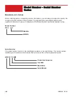
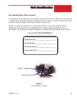
Страница 10: ...nds below specifically defines each significant character or group of characters of the Model Number and Serial Number codes Serial Number The serial number found on the identification plate is a ten digit format The model number identifies your machine and will ensure that you receive the correct replacement parts 436 01 11 005 Production Sequence Model Number PRO 430 MODEL Year Mfd Month Mfd Ser...

Страница 11: ... and is located on the rear lower left side of mainframe Refer to Figure 1 for serial number and model number location This plate should not be removed at any time Please record the information found on this plate below so it will be available should the identification plate become lost or damaged When ordering parts or requesting service information you will always be asked to specify the model a...

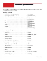
Страница 12: ...32x36 1829x813x914 436 72x38x36 1829x965x914 446 78x48x39 1981x1219x990 446SD 78x48x39 1981x1219x990 446SHD 78x48x39 1981x1219x990 Rotor Speed RPM 110 135 Finish Blade Standard Gearbox Standard Duty STD Fixed Guard Rings Standard Fixed Seat Frame Standard Powered Retardant Spray System Standard Spray System Capacity gal L 6 23 Steering System Dual Levers Gearbox Rotation Standard Battery 12 Volt S...

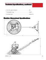
Страница 13: ...xi 055561 01 12 Technical Specifications continued Run Time Approximate hr 2 5 Transmission Type Clutch Drive Belt Type Kevlar Vee Machine Dimensional Specifications ...

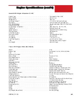
Страница 14: ...n Counterclockwise from PTO shaft side Compression Ratio 8 5 1 Carburetor Butterfly Float Type Ignition System Digital CDI with variable ignition timing Starting System Recoil electric Governor System Centrifugal Mass Type Air cleaner Dual element Fuel Tank Capacity 5 6 U S qts 5 3 liters Fuel Unleaded 86 octane or higher Dry Weight 55 lb 25 kg Honda GX340 Engine Information 11 HP Engine Type Air ...

Страница 15: ...rochoid Pump Oil Capacity 1 10 liters 0 40 effective Exhaust System Expansion Silencer with Cover Air Cleaner Dry Type with Paper Element Balancing System Single Counter Rotating Balancer Shaft Length 14 9in 378 2mm Width 16 6in 422mm Height 17 8in 453mm Dry Weight Recoil Start 78 3 lbs 35 5kg Engine Specifications cont d Honda GX390 Engine Information 13 HP Engine Type Air cooled 4 stroke OHV Bor...

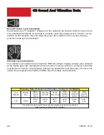
Страница 16: ...city value obtained at the handle grip while operating the ride on trowel on curing concrete in a manner most often experienced in normal circumstances Values were obtained from all three axes of motion The values shown represent the maximum RMS value from these measurements Summary Data Of Sound And Vibration Testing for CE Marking Test Machine Engine Type Distant Sound Press Operator Ear SPL Sou...

Страница 17: ...of Hazardous Waste Directive The Technical Construction file is maintained at Allen Engineering Corporation 819 South 5th St Paragould AR 72450 Telephone 800 643 0095 Facsimile 800 643 0097 The authorized representative is ab lin pro Mr Thomas Voeler Femvägsskälet 3 421 50 Västra Frölunda Sweden Tel 4631694910 Mobile 46 706694923 Fax 4631298876 Email tv lin pro se Signature of Authorized Person s ...

Страница 18: ...xvi 055561 01 12 INTENTIONALLY LEFT BLANK ...

Страница 19: ...1 1 055561 01 12 SECTION 1 SAFETY Section 1 SAFETY ...

Страница 20: ...TY 055561 01 12 CALIFORNIA PROPOSITION 65 WARNING Gasoline engine exhaust from this product contains chemicals known to the State of California to cause cancer birth defects and other reproductive harm State Regulations ...

Страница 21: ...atal injury or illness such as respiratory disease cancer birth defects or other reproductive harm If you are unfamiliar with the risks associ ated with the particular process and or material being cut or the composition of the tool being used review the material safety data sheet and or consult your employer the material manufacturer supplier governmental agencies such as OSHA and NIOSH and other...

Страница 22: ...h is essential to highlight that contains useful or important information EMERGENCY is used for the identification of safety equipment first aid or emergency egress locations NOTICE used to convey safety information on labels and signs CAUTION is indicative of a potentially hazardous situation which if not avoided may result in minor or moderate injury Potentially hazardous situations that could r...

Страница 23: ...e used on internal combustion engines A spark arrester is a device designed to prevent the discharge of spark or flames from the engine exhaust It is often required when operating equipment on forested land to prevent the risk of fires Consult the engine distributor or local authorities and make sure that you comply with regulations regarding spark arrestors ...

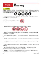
Страница 24: ...ar the work area of any debris tools etc that would constitute a hazard while the equipment is in operation No one other than the operator is to be in the working area when the equipment is in opera tion DO NOT use the equipment for any purpose other than its intended purposes or applications This equipment should only be operated by trained and qualified personnel 18 years of age and older Whenev...

Страница 25: ...res an adequate free flow of cooling air NEVER operate this equipment in any enclosed or narrow area where free flow of the air is restricted If the air flow is restricted it will cause injury to people and property and seri ous damage to the equipment or engine NEVER operate the equipment in an explosive atmosphere or near combustible materials An explosion or fire could result causing severe bod...

Страница 26: ... machine NEVER place your feet or hands inside the guard rings while starting or operating this equipment ALWAYS keep the machine in proper running condition Fix damage to machine and replace any broken parts immediately ALWAYS store equipment properly when it is not being used Equipment should be stored in a clean dry location out of the reach of children and unauthorized personnel A safety manua...

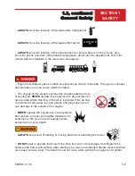
Страница 27: ...ilter Severe engine damage may occur Service air filter frequently to prevent engine malfunction NEVER tamper with the factory settings of the engine or engine governor Damage to the engine or equipment can result if operating in speed ranges above the maximum allowable DO NOT start the engine near spilled fuel or combustible fluids Fuel is extremely flammable and its vapors can cause an explosion...

Страница 28: ...fically cleared for such transport by the manufacturer NEVER hoist the trowel more than three feet off the ground with float pans attached Before lifting make sure that the lifting bales are not damaged Always make sure crane or lifting device has been properly secured to the lifting bales of the equipment ALWAYS shutdown engine before transporting NEVER lift the equipment while the engine is runn...

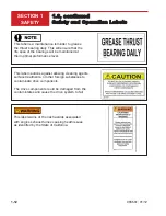
Страница 29: ...have maximum eye hearing hand and feet protec tion Also it highly recommends that the operator reads the manual This label identifies the lift locations on the machine No other locations or features on the machine are to be used as lifting points This will cause damage to the machine This label identifies the tank used for retardant spray agents i e water based retardants only on the machine NO OT...

Страница 30: ... The drive components could be damaged from the contamintates and cause the drive system to fail This label is a maintenance reminder to grease the thrust bearing daily This will ensure that the life span of the bearings will be maintained at their optimal preformance level This label warns of the risk hazards associated with engine exhaust fumes causing heath issues as identified by the State of ...

Страница 31: ...2 1 055561 01 12 SECTION 2 OPERATIONS Section 2 OPERATIONS ...

Страница 32: ...mind However it can present hazards if improperly operated and serviced Follow operating instructions carefully If you have any questions about operating or servicing this equipment please contact your Allen Engineering Dealer or AEC Customer Service at 800 643 0095 or 870 236 7751 ...

Страница 33: ... maintenance and trouble free use under some of the worst conditions Power is transferred from the engine to the gearbox input shaft via a V belt pulley drive system The pulley engages using a clutch See the Parts section of this manu al All Allen Engineering Walk behinds are equipped with a safety shutdown switch Operating time between fuel refills is approximately 2 1 2 to 3 hours with a rotor s...

Страница 34: ...ient amount of oil 3 If lubrication oil does not seep out as the drain plug is being removed fill with type Allen Oil Kit P N 048386 gearbox lubricant oil until the oil filler hole overflows V Belt Check A worn or damaged V belt can adversely affect the performance of the trowel If a V belt is defective or worn simply replace the Vbelt as outlined in the maintenance section of this manual Belt Gua...

Страница 35: ...2 5 055561 01 12 SECTION 2 OPERATIONS 2 3 Controls 2 1 3 4 5 6 7 8 9 10 11 12 13 14 15 ...

Страница 36: ...t located in front of the gearbox 8 Throttle Lever Controls engine speed Returns engine to idle when released 9 Trowel Lifting Point The trowel is equipped with a lifting bail that can be used to safely lift and move the trowel 10 Main Tube When disassembling components inside the tube exercise caution 11 Guard Ring NEVER put hands or feet inside guard ring while the machine is running 12 Engine T...

Страница 37: ... and smoothly 5 Fuel Valve Lever OPEN to let fuel flow CLOSE to stop the flow of fuel 6 Choke Lever Used in the starting of a cold engine or in cold weather conditions The choke enriches the fuel mixture 7 Air Cleaner Prevents dirt and other debris from entering the fuel system Remove wing nut on top of air filter cannister to gain access to filter element 8 Spark Plug Provides spark to the igniti...

Страница 38: ...lade speed is obtained 2 To maneuver the trowel gently lift up on or press down on the main trowel handle To move the machine to the operator s left lift up on the handle to move machine to the right push down on the handle 3 The best method for finishing concrete is to slowly walk backwards with the trowel guid ing the trowel from side to side This will cover all footprints on wet concrete 4 Reme...

Страница 39: ...h Adjustment Different pitch angles are needed as you work the different stages of the concrete When changing or setting pitch angle of trowel blades slow the machine down set the desired degree of pitch on the left side of the machine and then adjust the right side to match To increase the pitch turn the pitch control clockwise use the pitch indicator to adjust pitch equally on both right and lef...

Страница 40: ...2 10 SECTION 2 OPERATIONS 055561 01 12 Notes ...

Страница 41: ...3 1 055561 01 12 SECTION 3 SERVICE Section 3 SERVICE ...

Страница 42: ...erator s manual was supplied with the machine when it was shipped To service the engine pull the seat locking pin out and tilt seat back TABLE 3 1 1 CHECK LIST ITEM DAILY EVERY 20 HRS EVERY 50 HRS EVERY 100 HRS EVERY 300 HRS Grease towel arms ü Check oil level in gearbox ü Check engine oil level ü Check tighten external hardware ü Check drive belt for wear ü Check valve clearance ü Change engine o...

Страница 43: ...ll plug Add oil through hole opening Replace fill plug after proper level has been achieved Fill so that there is oil 1 2 way in the sight glass Use Allen Oil only 2 Each Gearbox has a grease fitting on top cover that must be greased 2 SHOTS ONLY every 300 operating hours Use only Mobilith SHC 220 Extended pressure grease FIGURE 3 2 1 FILL PLUG LOCATION FIGURE 3 2 2 GREASE FITTING LOCATION GREASE ...

Страница 44: ...ightness of the trowel arms The steps below descride the general procedure to remove the trowel arms to be aligned Make sure that there is no pitch in the blades before attempting to remove a trowel arm 1 Block up pressure plate A using a wooden block 2 Remove stabilizer ring from spider assembly only on available models 3 Remove blades from trowel arms 4 Loosen hex head cap screw B and remove it ...

Страница 45: ...3 5 055561 01 12 SECTION 3 SERVICE 3 6 continued Lift Lever Adjustment A B TROWEL ARM BLADE FIGURE 3 6 1 PRESSURE PLATE LOCATION FIGURE 3 6 2 FASTENER HARDWARE REMOVAL SPIDER BOSS ...

Страница 46: ...3 10 SECTION 3 SERVICE 055561 01 12 Notes ...

Страница 47: ...4 1 055561 01 12 SECTION 4 PARTS Section 4 PARTS ...

Страница 48: ...screws have blue LOC TITE applied at the factory If set screw is removed or loosened for any reason re apply blue LOC TITE All grease fittings are capped with CAP PLUG GC 5 AEC PN 015692 to protect the fitting If cap becomes missing or damaged replace it as soon as possible Anti Seize is applied at the factory to all drive line coupling gear box main and counter shafts and pitch control threaded r...

Страница 49: ...eplacement parts by the appropriate part number not the key number This manual contains an illustrated parts list for help in ordering replacement parts for your machine Follow the instructions below when ordering parts to insure prompt and accurate delivery 1 All orders for service parts include the serial number for the machine Shipment will be delayed if this information is not available 2 Incl...

Страница 50: ...4 4 SECTION 4 PARTS 055561 01 12 4 1 Illustration Fine Pitch Adjustment 1 10 11 9 6 7 5 4 8 3 2 ...

Страница 51: ...9 KNOB ADJUSTABLE HANDLE 1 3 015740 FSTN PIN SPIRAL 3 16 X 1 3 4 1 4 015741 SCREW SHAFT PITCH CONTROL 1 5 015742 THRUST BEARING 1 6 015743 BUSHING F PITCH CONTROL 1 7 015744 WASHER FINE PITCH CNTRL SPACER 1 8 015745 RING RETAINING 1 9 015746 BUSHING SLIDE 1 10 015747 PIN ROLL 3 16 X 1 3 8 SPIROL 1 11 015768 FSTN SHCS 1 4 20 X 1 4 HOLO 1 ...

Страница 52: ...4 6 SECTION 4 PARTS 055561 01 12 4 2 Illustration Positive Pitch Adjustment 10 22 2 6 9 15 20 12 18 14 1 4 5 3 6 17 7 19 16 13 3 11 8 22 ...

Страница 53: ...510 FITTING 1 4 28 NPT 45 GREASE 1 10 019427 KNOB BLK RD PLASTIC 1 7 8 1 11 024630 BUSHING 3 4x1x1 8 BRONZE 1 12 027946 SPROCKET LEVER PITCH 1 13 027948 BUSHING SUPPORT BRKT 1 14 027952 CABLE PITCH CONTROL LONG ASSY 1 028013 CABLE 44 25 POS PTCH SHRT HNDLE 1 15 027958 CLTCH POS PITCH ASSY 1 16 027961 BRKT LEVER PITCH CLUTCH 1 17 027963 COVER WELD T LEVER PITCH 1 18 028033 CHAIN 35 R V 13 25 19 029...

Страница 54: ...4 8 SECTION 4 PARTS 055561 01 12 4 3 Illustration 430 Edging Spider 032235 9 1 5 4 10 7 6 8 3 2 ...

Страница 55: ...nal Tooth Lock Washer Steel 3 8 in 4 3 015683 BOLT 3 8 16 X 7 8 DOG PT HEX HD CAP 4 4 015684 FSTN NUT HEX JAM 3 8 16 8 5 015686 FSTN SQHSS 3 8 16 X 1 4 6 015816 SPIDER 4 BOSS MACH CW STD 1 7 016920 SPRING CLIP UNIVERSAL SPIDERS 4 8 024755 FITTING 1 8 27 NPT 45 GREASE 4 9 028751 TROWEL ARM 750 STD SPIDER 4 10 033032 LIFT LEVER STD UNIVERSAL 4 ...

Страница 56: ...4 10 SECTION 4 PARTS 055561 01 12 4 4 Illustration 436 Spider 015893 6 11 8 5 4 1 9 3 2 7 10 ...

Страница 57: ... 3 8 4 3 015683 FSTN 3 8 16 X 7 8 DOG CAP SCREW 4 4 015684 FSTN NUT HEX JAM 3 8 16 8 5 015686 FSTN SQHSS 3 8 16 X 1 4 6 015688 FSTN 9 16 18 NF ADJ MACH SCRW 4 7 015816 SPIDER 4 BOSS MACH CW STD 1 8 015818 TROWEL ARM STD 36 SPIDER 4 9 016920 SPRING CLIP UNIVERSAL SPIDERS 4 10 024755 FITTING 1 8 27 NPT 45 GREASE 4 11 033032 LIFT LEVER STD UNIVERSAL 4 ...

Страница 58: ...4 12 SECTION 4 PARTS 055561 01 12 4 5 Illustration 446 Spider 024812 6 11 5 4 7 9 8 1 3 2 10 ...

Страница 59: ...LOCK 4 3 015683 BOLT 3 8 16 X 7 8 DOG PT HEX HD CAP 4 4 015684 FSTN NUT HEX JAM 3 8 16 8 5 015686 FSTN SQHSS 3 8 16 X 1 4 6 015688 FSTN 9 16 18 NF ADJ MACH SCRW 4 7 015816 SPIDER 4 BOSS MACH CW STD 1 8 016920 SPRING CLIP UNIVERSAL SPIDERS 4 9 024755 FITTING 1 8 27 NPT 45 GREASE 4 10 024794 TROWEL ARM STD 46 SPIDER 4 11 033032 LIFT LEVER STD UNIVERSAL 4 ...

Страница 60: ...4 14 SECTION 4 PARTS 055561 01 12 4 6 Illustration 446SD Spider 026588 9 8 7 10 1 5 4 11 6 2 3 ...

Страница 61: ... FSTN CABLT 1 2 13 X 1 1 2 GR8 4 11 033034 LEVER LIFT SD UNIVERSAL 4 OUR MISSION STATEMENT Our Mission is to provide superior quality products manufactured in a safe and efficient environment by highly trained and dedicated personnel on time deliveries and reactive knowledgeable customer service OUR QUALITY POLICY The Allen Engineering Team is fully committed to exceeding customer expectations for...

Страница 62: ...4 16 SECTION 4 PARTS 055561 01 12 4 7 Illustration 430 Edging Power Unit 037275 55 45 32 54 29 57 37 25 58 50 46 33 9 4 5 26 1 3 50 8 1 2 4 35 34 49 18 59 56 42 38 10 ...

Страница 63: ... PLASTIC CAP EC12 1 18 015694 PLUG W 1 RED PLASTIC TAPERD 4 19 015696 KEY 25x1 25 LG HARD RAD 1 20 015707 PULLEY 3 4 BOREx5 73 OD V GRV 1 21 015711 FSTN FHSCS 3 8 16 x 3 4 4 22 015821 CAP PRESSURE PLATE 1 23 015822 THRUST BEARING 1 24 015824 PLATE PRO RIDER WALKER PRESSURE 1 25 015987 GUARD BELT SMALL PLASTIC 1 26 016191 DECAL ALLOW ENG TO COOL 1 27 017264 YOKE TROWEL 1 28 018012 FSTN STD BLT 5 16...

Страница 64: ...4 18 SECTION 4 PARTS 055561 01 12 4 7 Illustration 430 Edging Power Unit cont d 32 53 52 48 20 27 14 15 17 19 16 12 13 6 39 40 41 44 43 47 30 ...

Страница 65: ...SYM WARNING 4 47 040860 BRACKET EDGER COVERS 430 436 4 48 041325 V BELT 1 49 041696 TROWEL BLADE 30 EDGER 6 X 10 5 4 50 042073L GUARD ROLLER LH 430 EDGER 2 51 042073R GUARD ROLLER RH 430 EDGER 1 52 047546 PAL NUT 1 4 20 4 53 048239 CLUTCH Ø3 4 ID BORE NR WE26 1 54 048379 DECAL ALLEN 4 1 2 x 1 1 2 1 55 048937 DECAL MFG BY ALLEN ENG 1 56 053448 DECAL LIFT HERE ONLY SP 1 57 053453 DECAL SPARK WARNING...

Страница 66: ...4 20 SECTION 4 PARTS 055561 01 12 4 8 Illustration 436 Edging Power Unit 043491 and 039212 57 58 34 56 28 43 55 31 59 30 6 5 44 1 4 51 47 19 50 60 9 51 35 10 26 52 45 46 36 27 3 2 ...

Страница 67: ...G PLASTIC CAP EC12 1 19 015694 PLUG W 1 RED PLASTIC TAPERD 4 20 015696 KEY 25x1 25 LG HARD RAD 1 21 015707 PULLEY 3 4 BOREx5 73 OD V GRV 1 22 015711 FSTN FHSCS 3 8 16 x 3 4 4 23 015821 CAP PRESSURE PLATE 1 24 015822 THRUST BEARING 1 25 015824 PLATE PRO RIDER WALKER PRESSURE 1 26 015893 SPIDER ASSY 900 SFC LH SOM 1 27 015987 GUARD BELT SMALL PLASTIC 5 5 HP 1 015703 BELT GUARD LARGE PLASTIC 9 HP 1 2...

Страница 68: ...4 22 SECTION 4 PARTS 055561 01 12 4 8 Illustration 436 Edging Power Unit cont d 38 39 40 42 41 48 32 15 16 18 17 29 8 12 13 14 54 21 49 61 25 23 24 ...

Страница 69: ...ER COVERS 430 436 4 49 041325 V BELT 5 5 HP 1 041324 V BELT 9 HP 1 50 041681 ROLLER COVER LH SOM FRONT 900 EDGER 2 51 041683 ROLLER COVER RH SOM FRONT 900 EDGER 2 52 041695 TROWEL BLADE 436 900 EDGER 6 X 14 4 53 047546 PAL NUT 1 4 20 4 54 048239 CLUTCH Ø3 4 ID BORE 5 5 HP 1 047843 CLUTCH 1 BORE 9 HP 1 55 048379 DECAL ALLEN 4 1 2 x 1 1 2 1 56 048937 DECAL MFG BY ALLEN ENG 1 57 049771 PLATE WALKBEHI...

Страница 70: ...4 24 SECTION 4 PARTS 055561 01 12 4 9 Illustration 436 Power Unit 035724 035726 035728 48 50 52 43 35 51 30 47 33 38 28 53 4 31 1 10 3 6 40 36 11 27 20 41 23 39 2 12 ...

Страница 71: ... PLUG W 1 RED PLASTIC TAPERD 4 21 015696 KEY 25x1 25 LG HARD RAD 1 22 015707 PULLEY 3 4 BOREx5 73 OD V GRV 1 029102 PULLEY BK90H LOW SPEED 1 23 015711 FSTN FHSCS 3 8 16 x 3 4 4 24 015821 CAP PRESSURE PLATE 1 25 015822 THRUST BEARING 1 26 015824 PLATE PRO RIDER WALKER PRESSURE 1 27 015893 SPIDER ASSY 900 SFC LH SOM 1 28 015987 GUARD BELT SMALL PLASTIC 1 015703 GUARD BELT LARGE PLASTIC 1 027242 GUAR...

Страница 72: ...4 26 SECTION 4 PARTS 055561 01 12 4 9 Illustration 436 Power Unit cont d 54 14 15 42 9 13 18 16 19 17 21 34 22 46 44 45 8 12 26 24 25 ...

Страница 73: ...LT 1 041353 V BELT LOW SPEED 1 45 047546 PAL NUT 1 4 20 4 46 048239 CLUTCH Ø3 4 ID BORE NR WE26 5HP 1 047843 CLUTCH 1 BORE NR WE25 9HP 1 47 048937 DECAL MFG BY ALLEN ENG 1 48 049771 PLATE WALKBEHIND LIFTING 1 49 053446 DECAL MADE IN USA SP 1 50 053448 DECAL LIFT HERE ONLY SP 1 51 053453 DECAL SPARK WARNING SP 1 52 056336 DECAL AEC 1 5 X 3 25 WHITE RED 1 53 056341 DECAL ALLEN OVAL 2 X 3 34 WHITE 1 ...

Страница 74: ...4 28 SECTION 4 PARTS 055561 01 12 4 10 Illustration 446 Power Unit 035732 035735 50 52 54 45 53 30 33 49 22 55 1 10 51 11 39 37 38 13 8 7 42 43 41 24 36 25 3 4 40 29 20 ...

Страница 75: ... 2 15 015678 PIN YOKE ARM 1 16 015690 WASHER RETAINING FOR TROWELS 1 17 015691 FSTN SHCS 1 2 13 X 1 1 2 RH 1 18 015692 CAP Ø1 4 RED GREASE 4 19 015693 PLUG PLASTIC CAP EC12 1 20 015694 PLUG W 1 RED PLASTIC TAPERD 12 21 015696 KEY 25x1 25 LG HARD RAD 1 22 015703 BELT GUARD LARGE PLASTIC 1 23 015707 PULLEY 3 4 BOREx5 73 OD V GRV 1 24 015711 FSTN FHSCS 3 8 16 x 3 4 4 25 015805 RING 446 STD STABILIZER...

Страница 76: ...4 30 SECTION 4 PARTS 055561 01 12 4 10 Illustration 446 Power Unit cont d 035732 035735 48 47 35 46 23 16 17 21 19 14 15 13 9 12 31 44 34 5 28 27 ...

Страница 77: ...37661 PLATE ADAPTOR 9 11 HP 1 037660 PLATE ADAPTOR 9 11 HP 1 43 037665 PLATE ADAPTOR 11 HP HO 1 44 037675 FSTN FENDER WASHER 3 8 X 1 1 4 4 45 039048 DECAL GEN PROTECTION WARNING 1 46 041324 V BELT 1 47 047546 PAL NUT 1 4 20 4 48 047843 CLUTCH Ø1 ID BORE NR WE25 1 49 048937 DECAL MFG BY ALLEN ENG 1 50 049771 PLATE WALKBEHIND LIFTING 1 51 053446 DECAL MADE IN USA SP 1 52 053448 DECAL LIFT HERE ONLY ...

Страница 78: ...4 32 SECTION 4 PARTS 055561 01 12 4 11 Illustration 446SD Power Unit 042037 54 56 58 46 1 53 52 5 1 13 57 59 55 14 40 3 7 23 29 36 35 33 30 16 10 8 32 41 38 37 ...

Страница 79: ...STYLE RETAINING 2 18 015678 PIN YOKE ARM 1 19 015690 WASHER RETAINING FOR TROWELS 1 20 015691 FSTN SHCS 1 2 13 X 1 1 2 RH 1 21 015692 CAP Ø1 4 RED GREASE 4 22 015693 PLUG PLASTIC CAP EC12 1 23 015694 PLUG W 1 RED PLASTIC TAPERD 4 24 015696 KEY 25x1 25 LG HARD RAD 1 25 015711 FSTN FHSCS 3 8 16 x 3 4 4 26 015821 CAP PRESSURE PLATE 1 27 015822 THRUST BEARING 1 28 015824 PLATE PRO RIDER WALKER PRESSUR...

Страница 80: ...4 34 SECTION 4 PARTS 055561 01 12 4 11 Illustration 446SD Power Unit cont d 042037 42 45 43 34 4 44 47 51 12 39 2 50 31 28 26 27 16 11 ...

Страница 81: ... 042057 CLUTCH WALK BEHIND 2 GROOVE 1 48 042058 SPACER 446SD 11 13Hp W B 2GR ENGINE 1 49 042060 SHIM 446SD 11 13Hp W B 2GR ENGINE 1 50 042065 BRKT 446SD 11HO 2GR BELT GUARD MTG 1 51 042070 V BELT B 30 2 52 048437 GUARD 446SD 2GROOVE CLUTCH BELT 1 53 048438 TAB 446SD 2GR BELT GUARD 1 54 049771 PLATE WALKBEHIND LIFTING 1 55 053446 DECAL MADE IN USA SP 1 56 053448 DECAL LIFT HERE ONLY SP 1 57 053453 ...

Страница 82: ...4 36 SECTION 4 PARTS 055561 01 12 4 12 Illustration 446SD TC Power Unit 055643 28 25 40 42 51 37 43 52 41 54 33 30 31 19 34 10 45 36 45 ...

Страница 83: ...G PLASTIC CAP EC12 1 19 015694 PLUG W 1 RED PLASTIC TAPERD 4 20 015696 KEY 25x1 25 LG HARD RAD 1 21 015821 CAP PRESSURE PLATE 1 22 015822 THRUST BEARING 1 23 015824 PLATE PRO RIDER WALKER PRESSURE 1 24 016094A TROWEL BLADE COMBO 8 X 18 AEC BLUE 4 25 016191 DECAL ALLOW ENG TO COOL 1 26 017264 YOKE TROWEL 1 27 017751 FSTN FW HARD A325 3 8 p 6 28 018967 HONDA 11 HP 1 29 020514 FSTN NUT STOVER LOCK 3 ...

Страница 84: ...4 38 SECTION 4 PARTS 055561 01 12 4 12 Illustration 446SD TC Power Unit cont d 055643 15 18 16 20 17 13 14 44 36 11 4 21 22 23 ...

Страница 85: ...6 055649 SPACER 4 47 055900 PULLEY DRIVER 1 48 055901 DRIVEN PULLEY 1 49 055902 BELT CVT F TEXAS WALKER 1 50 055903 EXT RETAINING RING 1 51 056336 DECAL AEC 1 5 X 3 25 WHITE RED 1 52 056341 DECAL ALLEN OVAL 2 X 3 34 WHITE 1 53 056458 PULLEY GUARD 1 54 056459 RING 446SD TC 1 55 056484 HHCS 5 16 24 X 4 1 2 1 56 058051 CLUTCH GUARD 1 57 058052 CLUTCH GUARD MNTG BRKT 1 58 058055 SPACER 3 4 X 5 32 X 1 ...

Страница 86: ...3 Illustration Standard Gear Box 015202 32 8 30 4 7 Torque to 22 Ft Lbs 9 25 10 11 27 26 12 6 24 Torque to 12 Ft Lbs 15 17 36 21 18 3 11 13 5 23 14 20 31 34 35 16 28 29 17 33 24 19 Torque to 12 Ft Lbs Grease this area for re assembly only ...

Страница 87: ...D 1 15 015221 CAP GEAR BOX END 1 16 015222 GASKET END CAP FLANGE 005 AS REQ 17 015660 O RING GEAR BOX END CAPS 2 18 015663 BEARING ANGULAR CONTACT 1 19 015670 SEAL OIL CR 7455V 1 20 015671 SEAL OIL CR 13661 1 21 015672 GAUGE 3 4 14 NPT PORTHOLE VIEW 1 22 015673 O RING 15 16x1 3 16x1 8 BUNA 1 23 015696 KEY 25x1 25 LG HARD RAD 1 24 017314 FSTN SHCS 1 4 20 X 5 8 8 25 020018 GASKET 003 THICK TOP COVER...

Страница 88: ...ustration Gear Box w Special Shaft TC 055647 32 8 30 4 7 Torque to 22 Ft Lbs 9 25 10 11 27 26 12 6 24 Torque to 12 Ft Lbs 15 17 36 21 18 3 11 13 5 23 14 20 31 34 35 16 28 29 17 33 24 19 Torque to 12 Ft Lbs Grease this area for re assembly only ...

Страница 89: ...HED 1 15 015221 CAP GEAR BOX END 1 16 015222 GASKET END CAP FLANGE 005 AS REQ 17 015660 O RING GEAR BOX END CAPS 2 18 015663 BEARING ANGULAR CONTACT 1 19 015670 SEAL OIL CR 7455V 1 20 015671 SEAL OIL CR 13661 1 21 015672 GAUGE 3 4 14 NPT PORTHOLE VIEW 1 22 015673 O RING 15 16x1 3 16x1 8 BUNA 1 23 015696 KEY 25x1 25 LG HARD RAD 1 24 017314 FSTN SHCS 1 4 20 X 5 8 8 25 020018 GASKET 003 THICK TOP COV...

Страница 90: ...4 44 SECTION 4 PARTS 055561 01 12 4 15 Illustration Handle Short Fine 034284 See Page 4 4 for Fine Pitch Adjustment Assembly 33 31 3 7 14 18 17 19 22 30 23 29 32 27 9 8 5 24 21 2 4 25 26 ...

Страница 91: ...HER FINE PITCH CNTRL SPACER 1 15 015746 BUSHING SLIDE 1 16 015747 PIN ROLL 3 16 X 1 3 8 SPIROL 1 17 015752 BLOCK CABLE SUPPORT 1 18 015753 PULLEY CABLE 1 19 015754 PIN 3 8 X 1 3 8 CABLE PULLEY 1 20 015768 FSTN SHCS 1 4 20 X 1 4 HOLO 1 21 015769 BAR CARRY F WALKBEHINDS 1 22 016691 CABLE PITCH CONTROL SHORT ASSY 1 23 018409 ASSY SWITCH SAFETY COMPLETE 1 24 034279 BLOCK CLAMP ADJ HAND R W 034277 1 25...

Страница 92: ...4 46 SECTION 4 PARTS 055561 01 12 4 16 Illustration Handle Short Positive 034450 See Page 4 6 for Positive Pitch Adjustment Assembly 23 16 15 17 33 6 37 39 12 31 18 36 19 30 35 38 32 14 29 3 8 1 ...

Страница 93: ...LLEY 1 18 015769 BAR CARRY F WALKBEHINDS 1 19 018409 ASSY SWITCH SAFETY COMPLETE 1 20 019427 KNOB BLK RD PLASTIC 1 7 8 1 21 024630 BUSHING 3 4x1x1 8 BRONZE 1 22 027948 BUSHING SUPPORT BRKT 1 23 027952 CABLE PITCH CONTROL LONG ASSY 1 24 027958 CLTCH POS PITCH ASSY 1 25 027961 BRKT LEVER PITCH CLUTCH 1 26 027963 COVER WELD T LEVER PITCH 1 27 028033 CHAIN 35 R V 13 25 028035 LINK MASTER 35 S 2 28 029...

Страница 94: ...4 48 SECTION 4 PARTS 055561 01 12 4 17 Illustration Handle Long Fine 034283 See Page 4 4 for Fine Pitch Adjustment Assembly 33 31 3 7 14 18 17 19 22 30 23 29 32 27 9 8 5 24 21 2 4 25 26 ...

Страница 95: ...HER FINE PITCH CNTRL SPACER 1 15 015746 BUSHING SLIDE 1 16 015747 PIN ROLL 3 16 X 1 3 8 SPIROL 1 17 015752 BLOCK CABLE SUPPORT 1 18 015753 PULLEY CABLE 1 19 015754 PIN 3 8 X 1 3 8 CABLE PULLEY 1 20 015768 FSTN SHCS 1 4 20 X 1 4 HOLO 1 21 015769 BAR CARRY F WALKBEHINDS 1 22 015748 CABLE PITCH CONTROL LONG ASSY 1 23 018409 ASSY SWITCH SAFETY COMPLETE 1 24 034279 BLOCK CLAMP ADJ HAND R W 034277 1 25 ...

Страница 96: ...4 50 SECTION 4 PARTS 055561 01 12 4 18 Illustration Handle Long Positive 034451 See Page 4 6 for Positive Pitch Adjustment Assembly 23 16 15 17 33 6 37 39 12 31 18 36 19 30 35 38 32 14 29 3 8 1 ...

Страница 97: ...LLEY 1 18 015769 BAR CARRY F WALKBEHINDS 1 19 018409 ASSY SWITCH SAFETY COMPLETE 1 20 019427 KNOB BLK RD PLASTIC 1 7 8 1 21 024630 BUSHING 3 4x1x1 8 BRONZE 1 22 027948 BUSHING SUPPORT BRKT 1 23 015748 CABLE PITCH CONTROL LONG ASSY 1 24 027958 CLTCH POS PITCH ASSY 1 25 027961 BRKT LEVER PITCH CLUTCH 1 26 027963 COVER WELD T LEVER PITCH 1 27 028033 CHAIN 35 R V 13 25 028035 LINK MASTER 35 S 2 28 029...

Страница 98: ...4 52 SECTION 4 PARTS 055561 01 12 4 19 Illustration Handle Short Fine 055638 18 14 13 15 21 24 17 27 20 See Page 4 4 for Fine Pitch Adjustment Assembly 28 25 ...

Страница 99: ...SLIDE 1 12 015747 PIN ROLL 3 16 X 1 3 8 SPIROL 1 13 015752 BLOCK CABLE SUPPORT 1 14 015753 PULLEY CABLE 1 15 015754 PIN 3 8 X 1 3 8 CABLE PULLEY 1 16 015768 FSTN SHCS 1 4 20 X 1 4 HOLO 1 17 015769 BAR CARRY F WALKBEHINDS 1 18 016691 CABLE PITCH CONTROL SHORT ASSY 1 19 034279 BLOCK CLAMP ADJ HAND R W 034277 1 20 034282 HANDLEBAR WDMT F ADJ HNDL PT 1 21 034286 EXTENSION WDMT F SHT HNDL F PT 1 22 034...

Страница 100: ...4 54 SECTION 4 PARTS 055561 01 12 4 20 Illustration Safety Switch Assembly 018409 12 5 10 13 14 1 4 2 9 2 9 3 15 6 7 8 11 ...

Страница 101: ...BER SAFETY SWITCH 1 5 018267 CLIP CONTACT PT SAFETY SWTCH 1 6 018324 HOUSIN SAFETY SWITCH MF 1 7 018326 COVER SAFETY SWITCH MF 1 8 018404 FSTN FHMS SLT BRASS 8 32 X 1 2 9 018406 FSTN NUT BRASS HEX 8 32 2 10 018407 BLOCK CONTACT FOR PT SAFE SWITCH 1 11 018623 FSTN FHMS BRASS 8 32 X 3 8 1 12 018624 FSTN RHMS SLT 8 32 X 1 1 13 034072 KNOB POSITIVE LOCK 1 14 034316 LEVER SAFETY SWITCH F PT 1 15 038947...

Страница 102: ...4 56 SECTION 4 PARTS 055561 01 12 Notes ...

Страница 103: ...055561 01 12 INTENTIONALLY BLANK ...

Страница 104: ...055561 01 12 YOUR TOTAL SOURCE FOR CONCRETE EQUIPMENT ...

Отзывы: