


ControlLogix AC (10-265V) DC (5-150V) Isolated Relay Module
11
Publication
1756-IN513D-EN-P - November 2003
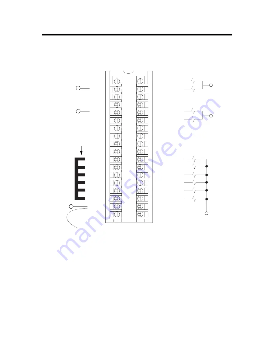
Wire the Module
You can only connect wiring to your module with an RTB or IFM.
After completing field-side wiring, secure the wires in the strain relief
area with a cable-tie.
1
2
3
4
5
6
7
8
9
10
11
12
13
14
15
16
17
18
19
20
21
22
23
24
25
26
27
28
29
30
31
32
33
34
35
36
30241-M
Non-isolated
wiring
Isolated wiring
Daisy chain to other RTBs
1756-OX8I
L1-0
L1-0
L1-1
L1-1
L1-4
L1-2
L1-2
L1-3
L1-3
L1-4
L1-5
L1-5
L1-6
L1-6
L1-7
L1-7
Not used
OUT-0 N.C.
OUT-0 N.O.
OUT-1 N.C.
OUT-1 N.O.
OUT-4 N.C.
OUT-2 N.C.
OUT-2 N.O.
OUT-3 N.C.
OUT-3 N.O.
Not used
OUT-4 N.O.
OUT-5 N.C.
OUT-5 N.O.
OUT-6 N.C.
OUT-6 N.O.
OUT-7 N.C.
OUT-7 N.O
Not used
L1
Jumper bar – Cut to length
(Part number 97739201)
DC-2 (-)
L2
L1-7
L2-0
DC-2 (+)
L1-0
NOTES:
1.
All terminals with the same name are connected together on the module. For
example, L1-0 can be connected to either terminal marked L1-0.
2.
Do not physically connect more than two wires to a single RTB terminal. When
you use the third L1-7 terminal to daisy chain to other RTBs, always connect the
daisy chain to the terminal directly connected to the supply wire, as shown.
3.
When using the
jumper bar
to daisy chain terminals together as shown, the
maximum current
you may apply to the module through a
single contact point
is 8A
.
4.
If separate power sources are used, do not exceed the specified isolation voltage.
Allen-Bradley Parts


