Rockwell Automation Publication VIEW-IN002C-EN-P - October 2018
11
Adapter Kit for PanelView 5000 and PanelView Plus 7 Performance Terminals
7.
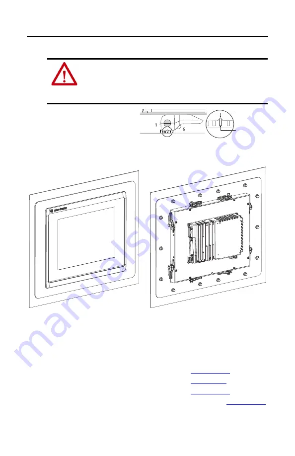
Inspect all mounting levers and verify that each lever is in the correct locked position.
The notch on the outside of
mounting lever shows the locked
position. The example at right
shows the mounting lever locked in
position 4.
The adapter plate and terminal are now installed in the panel.
Finish the Terminal Installation and Apply Power to the Enclosure
1.
To complete the power wiring, network cabling, initial startup, and configuration of the
terminal, follow the instructions in the user manual for your terminal:
• PanelView 5310 Terminals User Manual, publication
• PanelView 5500 Terminals User Manual, publication
• PanelView 5510 Terminals User Manual, publication
• PanelView Plus 7 Performance Terminals User Manual, publication
2.
To return power to the components in the enclosure, follow your approved sequence.
ATTENTION:
All mounting levers must be in the correct locked position and follow the
correct lever installation sequence to provide an adequate gasket seal between the
terminal and the adapter plate. Rockwell Automation assumes no responsibility for
water or chemical damage to the terminal or other equipment within the panel because
of improper installation.
Outer Notch on
Mounting Lever
Alignment Notch
on Terminal
Front View
Rear View


