10
Rockwell Automation Publication VIEW-IN002C-EN-P - October 2018
Adapter Kit for PanelView 5000 and PanelView Plus 7 Performance Terminals
5.
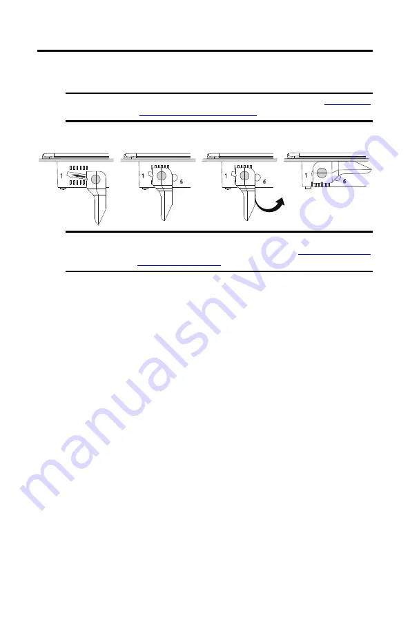
Insert the remaining levers in the terminal and rotate each lever until the flat side is in
contact with the backing plate and the gasket is slightly compressed.
If it is difficult to insert a mounting lever, press the bezel at the mounting lever position
to compress the gasket so you can insert the mounting lever.
6.
Readjust each mounting lever to its final lock position.
a. Rotate mounting lever one in the sequence away from the backing plate.
b. Slide the mounting lever to the final locking position.
If it is difficult to slide the mounting lever, press on the bezel at the mounting lever
position to compress the gasket so you can slide the mounting lever to the final
locking position.
If it is too difficult to slide a mounting lever to its final locking position, then slide
the mounting lever one position at a time until you are able to slide the mounting
levers to the final locking position.
c. Rotate the mounting lever until the flat side is in contact with the backing plate.
d. Lock the remaining mounting levers to their final position.
IMPORTANT
Install the mounting levers by the orientation sequence shown in
Orientation and Lock Sequence on page 8
.
IMPORTANT
Do not install the mounting levers in the final lock position yet. For example, if the
final lock position is 3, slide the lever to notch 4 or 5 (see
TIP
If the mounting levers are over torqued, the pin can break off. If a pin is broken, you
can turn the mounting lever over and use the lever in another location that meets
the orientation for the mounting lever.
1
2
3
4
Flat Side in Contact
With the Backing Plate


