H,410**+,<)1=/)$IJK#LM
!"#$%&'()
3–2
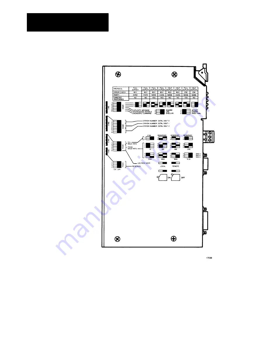
?./A'&()E0F@8#%.@+(@G(%"&(79.%8"(:,,&;<-.&,(@+(%"&(0123456(H@IA-&
Important:
The 1785-KE Series B uses the convention DOWN
(ON) = Binary 0, and UP (OFF) = Binary 1.
Страница 1: ...0 1 2345 678849 79 9 7 43 A6 B C7B D E33 9FG 3 1...
Страница 2: ...I 1 1 1 1 1 1 1 1 1 1 1 1 1 1 1 1 1 1 1 1 1 1 1 1 1 1 1 1 1 1 1 1 1 1 1 8Q 4 38 48 48 R I 1 1 1 1 1 1 1 1 1 1 1 1 1 1 1 1 1 R U 9D LIV L0A0L S 8T B 3 A 1 1 1 1 1 1 1 1 1 1 1 1 1 R U 9D L0V O P Q R D...
Страница 3: ...1 1 1 1 1 1 1 1 1 1 2S L0 E8 4 I 1 1 1 1 1 1 1 1 1 1 1 1 1 1 1 1 1 1 1 1 1 1 1 1 1 1 1 1 2S L0 E8 4 IJ 1 1 1 1 1 1 1 1 1 1 1 1 1 1 1 1 1 1 1 1 1 1 1 1 1 1 1 1 2 4Q _ 5 48 IK 1 1 1 1 1 1 1 1 1 1 1 1 1...
Страница 4: ...F3 H 1 1 1 1 1 1 1 1 1 1 1 R U 9D LHV F R4 T S 8T 4 38 48 1 1 1 1 R U 9D L V L0A0L 4 38 48 8 O Q84 4 8 1 7438 8Q IJKHLM 74 39 J 1 1 1 1 1 1 1 1 1 1 1 1 1 1 1 1 1 1 1 1 1 1 1 1 1 1 7 T 8Q 488 48 4 U I...
Страница 5: ...E troubleshooting your 1785 KE For more information on programming and troubleshooting Data Highway Plus and Data Highway interface modules refer to the Data Highway Data Highway Plus Protocol and Com...
Страница 6: ...e on the side of the module 42 A B 6 C D 1 A 01 2334 5 6 7 18 9 6 6 4 1 0 3 0 1 0 6 7 18 A04 66 1 0 B0 B 60 1 10 60 1 03 C D 01 2334 5 6 7 18 9E A 6 6 4 1 0 3 0 1 0 6 7 18 A04 66 1 0 B0 B 1 3406 03 C...
Страница 7: ...r understanding and use of the product The 1785 KE Data Highway Plus RS 232 C Interface Module is part of the Data Highway Plus product family Related products include 8 9 16 29 G1C4 H 1 E G 8 04 1 E...
Страница 8: ...nts 8142 6 9 F 8142 6 9 G1C4 H 1 E G 8 H B 4B G H403 1 1 QRUVLMDX 1 E G 8J 1 E G 8 H H4010 0 3 50 3 K 1 4Y QRRSLXDVDQX 1 E G 8 5 7 2 7 8 3 P 1 1 0 QRRSLXDMDQ The publications in the table above are av...
Страница 9: ...gent RS 232 C asynchronous device to an Allen Bradley Data Highway Plus network The 1785 KE gives you a choice of full duplex unpolled or half duplex polled protocol on its asynchronous link Figure 2...
Страница 10: ...and expansion if you want to add more nodes later Typically you would use Data Highway Plus to connect PLC 5s that need to communicate with each other frequently For example you would use Data Highway...
Страница 11: ...face module The Data Highway Plus cables consist of a trunkline that can be up to 10 000 feet long and droplines that can be up to 100 feet each You can use your Data Highway Plus to connect such node...
Страница 12: ...lus K O L Both Data Highway Plus and the 1785 KE s RS 232 asynchronous link require two layers of software to enable communication to take place The layers are defined as follows Application layer con...
Страница 13: ...on you need to program the software layers for your computer and troubleshoot your network K 9 C The Data Highway Plus link has a communication rate of 57 600 bits per second The Data Highway Plus imp...
Страница 14: ...col is similar to full duplex in most respects Two major differences are Half duplex protocol provides for polling of slave stations Half duplex protocol does not allow embedded responses Half duplex...
Страница 15: ...buffering commands retries due to noise on the network If your application requires that commands be delivered in a specific order your logic must control the initiation of one command at a time on th...
Страница 16: ...nk with a modem remote mode half duplex slave protocol option These are discussed in more detail later in Chapter 5 Communicating through the 1785 KE Module A short discussion of each application foll...
Страница 17: ...f duplex for the RS 232 C link Figure 2 4 shows an example of using a 1785 KE series B to connect two Data Highway Plus networks over a point to point modem link You must set the 1785 KE for full dupl...
Страница 18: ...e of using the 1785 KE series B to connect a Data Highway Plus node such as a PLC 5 to a multidrop network The PLC 5 acts as a slave on the multidrop link You must set the 1785 KE for half duplex prot...
Страница 19: ...s B version of the 1785 KE module uses different communication option switches has a different front cover and has different Data Highway Plus connectors than the Series A version This chapter describ...
Страница 20: ...H 410 1 IJK LM 3 2 A E0 F 8 G 79 8 0123456 H IA Important The 1785 KE Series B uses the convention DOWN ON Binary 0 and UP OFF Binary 1...
Страница 21: ...ing table shows you how to set switches 1 2 and 3 for the module options you require G M A L 7 8 N 8 L 6 8O L N L 6 II I P 7 7L40 79 8 0 J 2 72E N O 6 6 P QRSST P QRSST P QRSST 2 72E N O G 6 5 QR5T P...
Страница 22: ...odule uses and recognizes the following handshaking signals data set ready DSR request to send RTS clear to send CTS data carrier detect DCD data terminal ready DTR G M A L N 7 79 8 3 24 0 74 0 4 0 4...
Страница 23: ...gits 1 and 2 are used to set a Data Highway Plus node address for the 1785 KE module The node address is an encoded 2 digit octal number that identifies the 1785 KE module as a unique node on Data Hig...
Страница 24: ...QR5T 5 QR5T U 5 QR5T 5 QR5T 5 QR5T 5 QR5T 5 QR5T P QRSST 5 QR5T 5 QR5T P QRSST 5 QR5T P QRSST 5 QR5T 5 QR5T P QRSST 5 QR5T 5 QR5T P QRSST P QRSST 5 QR5T P QRSST P QRSST F P QRSST 5 QR5T 5 QR5T F P QR...
Страница 25: ...and 2 as follows A E3 7 S T 9 N A U I II 1 B8 S X VH 7 G 8 S W K B8 S 0 7 9 8 4 3 U E U EQ U E3 5 QR5T P QRSST P QRSST B8 S J VF 7 G 8 S W K B8 S J 7 9 8 R 4 2 U ER U E1 U E2 I P QRSST P QRSST P QRSS...
Страница 26: ...must be DOWN for 57 6 Kbit communication rate You use switches 3 4 and 5 to set the communication rate for the RS 232 C link between your device and the 1785 KE figure 3 6 Use the following table to...
Страница 27: ...Q Y YFT 3 861 867 P QRSST Communications to a 1785 KE Series A is the same as that to a 1785 KE in local mode i e when the 1785 KE Series B is in local mode it functions the same as a 1785 KE Series A...
Страница 28: ...dule in an Allen Bradley Bulletin 1771 I O rack follow these steps 1 Perform an orderly power down of the I O rack and its controlling PLC processor WARNING Remove system power before removing or inst...
Страница 29: ...H 410 1 IJK LM 3 11 The 1785 KE module has 3 connectors on its front edge figure 3 8 A E2 K 8 0123456 H O 8 0123456...
Страница 30: ...unk drop configuration for details on how to construct the dropline refer to the Data Highway Cable Assembly and Installation Manual publication 1770 6 2 1 A E 8 0123456 S T 9 N A U 9 O If the 1785 KE...
Страница 31: ...up your 1785 KE module To power up your module perform an orderly power up of the 1 0 rack and system PLC At power up the 1785 KE module runs tests to check the integrity of its internal memory timer...
Страница 32: ...device to the RS 232 C PORT connector figure 4 1 on your 1785 KE module The RS 232 C PORT connector a female 15 pin D shell does not conform strictly to the RS 232 C standard which specifies a 25 pin...
Страница 33: ...opto isolater circuit with an input and return line at the RS 232 C port All other signals on the RS 232 C port are driven and received by standard RS 232 C interface circuits which have maximum driv...
Страница 34: ...CG F FB B HI2 H NE E EKO 5 3 F FB B I2 H NE E EKO 51 For definitions of each signal refer to Appendix B When communication option switch 5 of switch assembly SW 1 handshaking enable disable is set DO...
Страница 35: ...ns the module s GND must be connected to the GND of the modem or computer RXDRET must be jumpered to GND at the module TXDRET should be left open Note that this type of connection does not provide ele...
Страница 36: ...nly The 1770 CG cable is 16 5 feet long If you need a longer cable or a male female adapter cable you can construct your own according to the wiring diagram in Figure 4 2 Make sure that the cable leng...
Страница 37: ...section earlier in this chapter entitled Electrical Characteristics of the RS 232 C Port For information on how to construct a longline cable for connection to a 1771 KG module refer to figure 4 3 177...
Страница 38: ...010 2 3 4 5678 9 4 7 0 5 89983 R H L0M 0 89953 Q 899 3 Q H L0M...
Страница 39: ...and the RS 232 C compatible connector on the modem Connect the cable shield at one end only The 1770 CP cable is 16 5 feet long If you need a longer cable or a male female adapter cable you can const...
Страница 40: ...ent mode data is passed over the link without being modified Note If handshaking is enabled via the SW 1 switch selection discussed in Chapter 3 and the DCD signal is lost for more than approximately...
Страница 41: ...ected to the phone lines The module serving as the data terminal equipment DTE controls the modem through the DTR DSR and DCD signals The module incorporates timeouts and tests to properly operate the...
Страница 42: ...to monitor the DCD line If DCD goes off the module restarts the timeout If DCD is not restored within the timeout the module initiates the hangup sequence This feature allows the remote station to re...
Страница 43: ...ier mode they only switch their carriers on when they transmit data The RS 232 C handshaking lines are used to control the switching of the carrier for a message transmission as follows figure 4 6 Req...
Страница 44: ...010 2 3 4 5678 9 4 13 0 W Q X M A Y EJ EE TE 1 2Z 2Z L 6 6...
Страница 45: ...tion and in Appendix B supporting the baud rate of your module operating on a multidrop link operating in switched carrier mode under handshake control interfacing to an asynchronous device operating...
Страница 46: ...together over a point to point modern link remote mode full duplex protocol connecting a Data Highway Plus node such as a PLC 5 as a slave on a multidrop link through a modem remote mode half duplex...
Страница 47: ...cessor Addressing for further background information on communicating from a computer to a PLC 5 AI 5 In this example we show the computer sending the following commands to the PLC 5 PLC 2 read and wr...
Страница 48: ...nd to the 1785 KE DLE STX DST SRC CMD STS TNS TNS ADR ADR DATA DLE ETX BCC 10 02 29 20 08 00 44 01 28 00 22 11 44 33 66 55 88 77 10 03 DE 2 1785 KE responds to computer DLE ACK 10 06 3 1785 KE sends c...
Страница 49: ...45 01 28 00 08 10 03 40 2 1785 KE responds to computer DLE ACK 10 06 3 1785 KE sends command to the PLC 5 The 1785 KE sends the command onto Data Highway Plus and the PLC 5 node at address 51 octal 4...
Страница 50: ...S TNS TNS FNC PO PO TT TT ADDRESS DATA DLE ETX BCC 10 02 29 20 0F 00 46 01 00 00 00 04 00 0F 00 0A 0F 00 22 11 44 33 66 55 88 77 10 03 D1 2 1785 KE responds to computer DLE ACK 10 06 3 1785 KE sends c...
Страница 51: ...TNS FNC PO PO TT TT NL N 1 0 1 5 NL SIZE DLE ETX BCC 10 02 29 20 0F 00 47 01 01 00 00 04 00 00 24 4E 31 30 3A 31 35 00 08 10 03 E0 2 1785 KE responds to computer DLE ACK 10 06 3 1785 KE sends command...
Страница 52: ...7 8 9 5 7 Figure 5 2 shows application involving communication between two Data Highway Plus networks through a full duplex link between two Series B 1785 KE modules 0 J 0 1 0 A B K RB G JH 0 S 1 0 A...
Страница 53: ...ata Highway Plus networks In the following examples we send PLC 5 read and write commands from a PLC 5 on Data Highway Plus 1 node address 010 to a PLC 5 on Data Highway Plus 2 node address 012 AI 5 M...
Страница 54: ...truction with the parameters shown below Also you must set up the message instruction for continuous mode by toggling bit N 10 0 11 to ON 87TTGU7 VKT1NL 1VCK G1G 8CKV1CN CN CK1NCI SIC 6 K2WHW 8 43 A9...
Страница 55: ...typing DISPLAY MONITOR N7 0 2 Change any value in word locations 0 through 7 in this file 3 The values appearing in word locations 10 through 17 should be the same as the values in word locations 0 th...
Страница 56: ...ies B The 1785 KE acts as a slave on the multidrop and listens for messages addressed to a PLC 5 on its Data Highway Plus link Thus the master can send a message addressed directly to a PLC 5 and the...
Страница 57: ...plication the 1785 KE has each of the following a Data Highway Plus address on the Data Highway Plus link a slave node address on the master slave multidrop network A single 1785 KE node address used...
Страница 58: ...PLC 5 with Data Highway Plus address 011 octal The master sends the message to the PLC 5 address 011 octal The 1785 KE recognizes the address as one of the addresses on the Data Highway Plus link and...
Страница 59: ...0123456 7 8 9 5 14 PLC 2 Program Example Rungs 8 through 11 are timer values to write to and then read from the PLC 5...
Страница 60: ...44 9 4M X I 8 43 8 K00 _ 9 Y c 9 C 9 C KbK KbQ _ 9 S 99 A S 43 R 9 0M _8 9 9 9 C 2 00 _8 9 Y b 8 44 9 4M X I 8 8 43 8 00 _ 9 Y c 9 C R 9 C S S 43 R 9 K0M _8 9 9 9 C 2 00 _8 9 S 99 A 8 S 8 9 C Kbb Kb1...
Страница 61: ...T50 message instructions necessary to send PLC 2 Unprotected Read and Unprotected Write commands from the PLC 5 address 011 octal to the master address 014 octal through the 1785 KE AI 5J L 9 M This e...
Страница 62: ...n below Also you must set up the message instruction for continuous mode by toggling bit N30 20 11 to ON 87TTGU7 VKT1NL 1VCK G1G 8CKV1CN CN CK1NCI SIC 6 KOWHJW 8 43 A9 B88 CC D E 69 C 9 D F G F HI 9 J...
Страница 63: ...his case the PLC 5 sends the command to local destination address 023 remote destination address 011 The command remains in the 1785 KE address 023 buffer until the master polls address 013 The 1785 K...
Страница 64: ...11 octal integer file 7 word locations 0 through 7 Program a message MSG instruction with the parameters shown below Also you must set up the message instruction for continuous mode be toggling bit N3...
Страница 65: ...th the parameters shown below Also you must set up the message instruction for continuous mode by toggling bit N30 20 11 to ON 87TTGU7 VKT1NL 1VCK G1G 8CKV1CN CN CK1NCI SIC 6 K2WHJW 8 43 A9 B88 CC D E...
Страница 66: ...alues in word locations 0 through 7 Important These PLC5 to PLC5 examples are for testing only Toggling the continuous bit to ON generates high network traffic which in most cases is not necessary A 0...
Страница 67: ...he master The valid range of addresses on Data Highway Plus is 00 77 octal 0 T GBB D TM5J C 0 W 8 9 G99 BB 7 B 0 1 B C 0 2 H T B B 2 J K 2 K J K J _LJ J _LJ 0 J _LJ X _L M X _L J _LJ Q X _L X _L Impor...
Страница 68: ...ts of the 1785 KE s address on the multidrop network Octal Digit 0 is a multidrop address expansion digit It sets the most significant highest digit of the 1785 KE multidrop address If you need to use...
Страница 69: ...ure shows that all of the 1785 KE s have address 21 octal on their respective DH networks The PLC s have addresses of 11 and 12 on their DH networks By setting Digit 0 you change the address as seen b...
Страница 70: ...es and and the diagnostic indicators of other Data Highway Plus and Data Highway modules refer to the Data Highway Data Highway Plus Protocol and Command Set Reference Manual publication 1770 6 5 16 T...
Страница 71: ...9 9H9 18 109 9 K9 0 009 1 089 EQ RSR F 3 UI 08 3 80 9 IIA 1891 089 1 K39 1 910 I K39 K39 F5 E 28 MF2G V 8 7 9 P 0 I07 9T H9 EENE M0 79 A 08 3 80 I3 89 I 089 79 09 0 P 09 0B 1891 I 09 3 9 BA 0 9 A I 7...
Страница 72: ...ters you must issue a Diagnostic Read command This command can only be sent from a device connected to a Data Highway Plus module that supports an asynchronous port that can format the diagnostic comm...
Страница 73: ...ounter bytes and what they contain 5 4 NL E G 5 4 54 246E R S R S R R A RR RSA R R A R R A R R A S S A SR SS S 919 H9 MF 7 08 K FEF 0 9 0 9X 9 7 08 MF 919 H9 0 0 90 9 9X8 09 YM _ 339 3 0 1 3 9 0 919 H...
Страница 74: ...1 3 0 K9 9 0 1 0 I 9 3 9 08 0 1 3 0 K9 I 7 9 1 0 I 9 9 919 H9 1 0 I MF 9 0 1 0 I YM 9 0 1 0 I Y 919 H9 1 0 I 90 919 H9 MF 9 1 0 I Q24 P QNCT 919 H9 1 0 I 9 9 9 1 0 I 9 9 K 09 KB V Y 1 0 I 9 9 K 09 KB...
Страница 75: ...50 Terminal 9 pin male EIA D shell connector Asynchronous RS 232 C 15 pin female EIA D shell connector Cabling Asynchronous RS 232 C Data Terminal Interface Cable cat no 1770 CG or equivalent or Modem...
Страница 76: ...4 3A 55 3 4 7 7 3 4 G7 5 O1P 2 4 3 55 3 D 8 E 6 3 7 3 4 3 7 3 3 3 3 7 573 N 1 1D Q5 R 45 7 573 QP1 7 3 4 8 7 B 5 4 E 7 573 7 E45 4 1 S3 H4 3 T 3 53 3 8 4 7 573 E 1 3 4 35 3 5 R 45 7 573 D 7 7 E E 3 3...
Страница 77: ...5 B 3 7 7 7 R E H N9 7 CYI 7 3 4 G7 5 UP1 7 IJKLYM 4 7 G E 3 3 4 1 3 3 3 5 35 3 3 G D 3 6 3 3 H E 4 D G H V4 5 3 8 7 3 4 1 2 4 3Y 55 3 D G 734 3 H 4 7 573 366Y733R1 8 6 4 7 4 E 63 1 2 3 3 3 4 3E E 34...
Страница 78: ...ectors The following sections describe the differences for each of these areas The Series A module operates like a Series B module in local mode If you are replacing a Series A 1785 KE with a Series B...
Страница 79: ...you to select various communication options The switch assemblies and their corresponding options are C B C E FG H8 C 8EE9 8 8 8 G 80 9 0 0 7 6 80 4 6 5 A BC D6 E FGGH 80 I 80J 45 6DE 80 A4 7 B4DD6 B...
Страница 80: ...how to set switches 1 2 and 5 for the module options you require QK F89 B 8 8 8 8 L C 8 C O G B C F G L C E 8 G C L40 B C G 8 8 8 G G 8 G 0 M 3 677 56L7 N O 4 4 FGG FGG FGG 677 56L7 N O P 4 FQ FGG FGG...
Страница 81: ...4 determines whether the RS 232 C port on the Series A module uses and recognizes the following handshaking signals data set ready DSR requests to send RTS clear to send CTS data carrier detect DCD da...
Страница 82: ...id node numbers for the Series A module are 00 to 77 octal Figure C 4 shows you how to set the node number using switch assemblies SW 3 and SW 4 Use the switches in assembly SW 3 to set the first left...
Страница 83: ...C 8 B C E F L43 Important You must set both switches ON for SW 5 This is the setting for a communication rate of 57 600 bits per second on the Data Highway Plus B C E F L4TG A 4MNM4 8EE9 8 A U 8 8EE Y...
Страница 84: ...lletin 1771 I O rack If you are using a dropline trunkline configuration you must mount the 1785 KE module within 100 cable feet of the Data Highway Plus trunkline When you are connecting the module d...
Страница 85: ...012 34567 C 8 The 1785 KE module has 3 connectors on its front edge figure C 7 H 9 I1 PC 8 8 8 C 0123456 7 O 8 8 8 C 0123456...
Страница 86: ...mbly and Installation Manual publication 1770 6 2 1 You can use the center connector labeled PEER COMM INTFC to connect your 1784 T50 terminal to Data Highway Plus You must use a cable with the pinout...
Страница 87: ...e file number that corresponds to the decimal equivalent of the PLC 2 s octal node address For example a PLC 2 with a node address of 012 octal will read data from and write data to file number 10 012...
Страница 88: ...dule with a node address of 000 to 010 octal to communicate with a PLC 5 using PLC 2 commands the module must be able to properly communicate to the corresponding file type listed in the previous tabl...
Страница 89: ...e specifications AAA beginning word addresses in octal of the remote node processor for read write operation BBB beginning word address in octal of the local node processor for read write operation CC...
Страница 90: ...error code The following table summarizes the addressing levels of the PLC 3 and PLC 5 5 B 456GH 93 F 45678 93 F 3 H5I J 6 K 5 5 572 G H5I J K 5 5 572 G 4 B L M 2 N097 90 7 3 O 3 G 6 J P2 9 8 M 2 J07C...
Страница 91: ...ws a PLC 3 message instruction with a PLC 5 address A computer can communicate with a PLC 5 on Data Highway Plus using the 1785 KE module The table below gives a summary of PLC 5 data table areas base...
Страница 92: ...E5 E 952 V0 F52 1 E 52 5 1 E 9 0 W 15 9 02 T M L59 2 S 1 E 9 0 E 9 0 W 52 5 4 S E 9 0 X 02 5 1 9 5 X ABC 1 2 3 4 52 K 3 952GT Y 0 5 E5 E 1502 1 2 5 D 1 2 5 ABC 7D 0 5 K IF 4567 6 3 L F 9 995 T ABC B...
Страница 93: ...OF 9 OF A BO O E O B O O58 ON9 F B98 P9 E C Q QG58 Q 7 H 9 R9 E 5 R 99 9 R 9E S S G T G S G 5 U 9 U U 9 U 9 U 9 U 5 V E V 8 V T 9 T D W9 4 5 49X Y9 F9 Y9D Z9 Y D 5 C 9 F 88 9 G 9 B B E B OU7 7 7 G 8 9...