Allen-Bradley 1783-BMS06SA Скачать руководство пользователя страница 16

16

Rockwell Automation Publication 1783-IN016B-EN-P - March 2019

Stratix 5700 Ethernet Managed Switches

Connect to 10/100 and 10/100/1000 Ports

The switch 10/100/1000 ports automatically configure themselves to operate at the speed of attached devices. If the attached ports do not support 
autonegotiation, you can explicitly set the speed and duplex parameters. Connecting devices that do not autonegotiate or that have their speed and 
duplex parameters that are manually set can reduce performance or result in no linkage. 

The Auto-MDIX feature is enabled by default. Unless this feature is disabled, you can use either straight-through or crossover cables to connect to 
other devices on the network.

To maximize performance, choose one of these methods for configuring the Ethernet ports:

• Let the ports autonegotiate both speed and duplex

• Set the port speed and duplex parameters on both ends of the connection

Connect to 10BASE-T, 100BASE-TX, or 1000BASE-T Ports

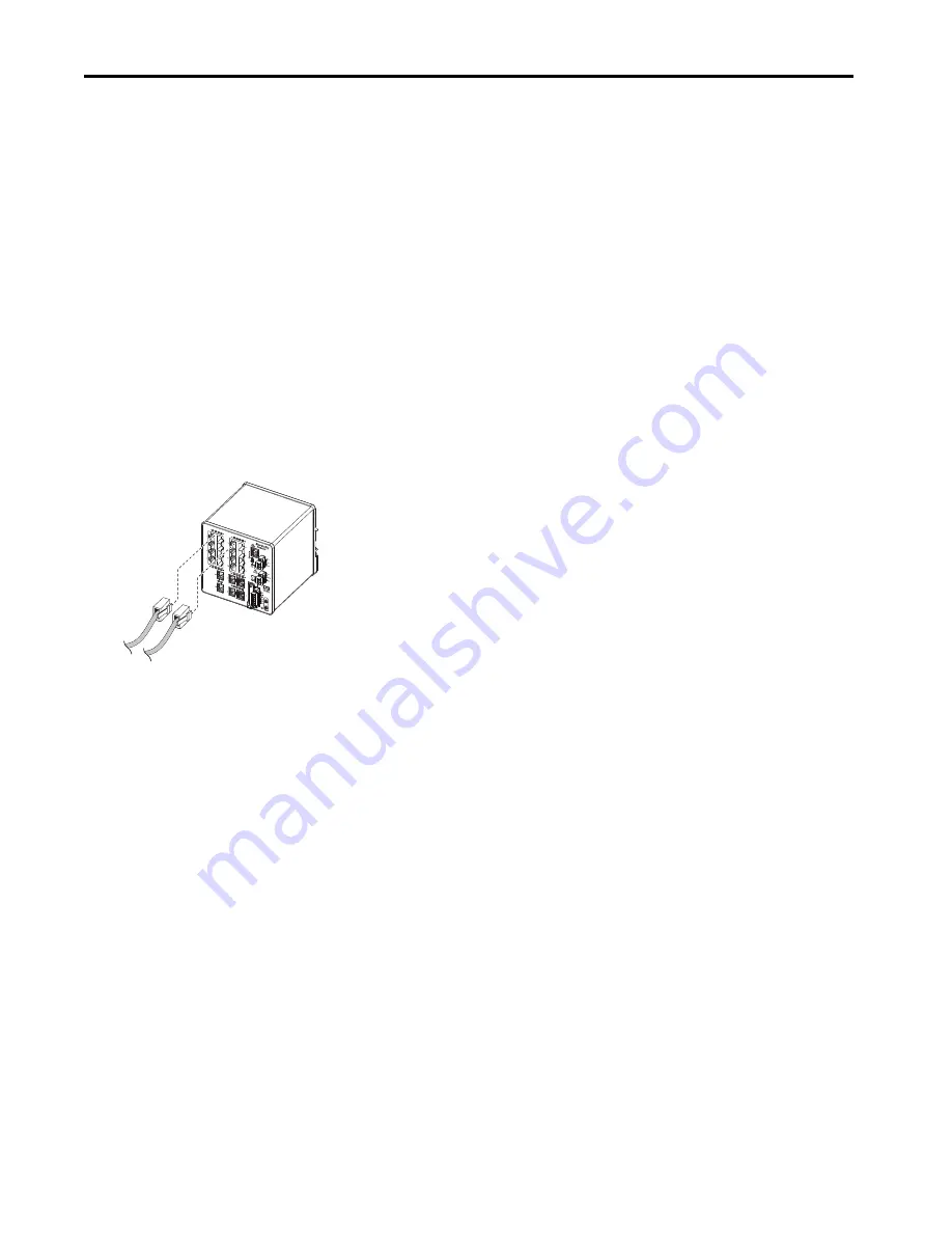
To connect to 10BASE-T, 100BASE-TX, or 1000BASE-T ports, follow these steps.

1.

Choose one of these options to connect a device:

• When connecting to workstations, servers, and routers, connect a straight-through cable to an RJ45 connector on the front panel.

• When connecting to 1000BASE-T-compatible devices, use a twisted four-pair, Category 5e or higher cable.

2.

Connect the other end of the cable to an RJ45 connector on the other device. 

The port status indicator turns on when both the switch and the connected device have an established link.

The port status indicator is amber while Spanning Tree Protocol (STP) discovers the topology and searches for loops. This can take up to 
30 seconds, and then the Port status indicator turns green.

The following conditions can prevent the port status indicator from turning On:

• The device at the other end is not turned On.

• A problem exists with a cable or the adapter that is installed in the attached device. 

3.

Reconfigure and restart the connected device if necessary.

4.

Repeat this procedure to connect each device.

32291-M

Содержание 1783-BMS06SA

Страница 1: ...6 Site Requirements 7 Mount the Switch 7 Ground the Switch 8 Wire the DC Power Source 9 Install the Power Connectors on the Switch 10 Wire External Alarms 11 Install the Alarm Relay Connector on the S...

Страница 2: ...fettuare interventi di manutenzione su di esso leggere il presente documento ed i documenti elencati nella sezione Altre risorse riguardanti l installazione la configurazione ed il funzionamento dell...

Страница 3: ...inaresidentialenvironment itmaycauseradiofrequencyinterference Undersuchcircumstances the user may be requested to take appropriate countermeasures Prevent Electrostatic Discharge ATTENTION Thisequipm...

Страница 4: ...as defined in EN 60664 1 when applied in Zone 2 environments The enclosure must be accessible only by the use of a tool This equipment shall be used within its specified ratings defined by Rockwell Au...

Страница 5: ...ARNING RISQUE D EXPLOSION Couper le courant ou s assurer que l environnement est class non dangereux avant de d brancher l quipement Couper le courant ou s assurer que l environnement est class nondan...

Страница 6: ...T2000 ERG 2001 or equivalent 5 3 mm2 10 AWG copper ground wire such as Belden part number 9912 or equivalent Wire stripping tool For panel mounting without a DIN rail M5 or 10 24 or 10 32 bolts or scr...

Страница 7: ...theSwitch The switch ships with a spring loaded latch on the rear panel for mounting on a DIN rail To mount the switch on a DIN rail follow these steps 1 Position the rear panel of the switch directly...

Страница 8: ...ratcheting torque screwdriver with a Phillips head Store the ground screw for later use 2 Use the guidelines from the manufacturer to determine the wire length to be stripped 3 Insert the ground wire...

Страница 9: ...0 5 mm 0 02 in Do not strip more than 6 8 mm 0 27 in of insulation from the wire Stripping more than the recommended amount of wire can leave wire exposed after installation 5 Loosen the two captive s...

Страница 10: ...and an optional secondary power source InstallthePowerConnectorsontheSwitch To install the switch power connectors to the front panel of the switch follow these steps 1 Insert one power connector into...

Страница 11: ...ction are required to complete one input alarm circuit You must provide either an NO or an NC dry contact to complete the alarm circuit between reference ground and IN1 or IN2 The three remaining conn...

Страница 12: ...or the external alarm device into the connections that are based on an alarm input or output circuit setup See Table on page 11 5 Use a ratcheting torque flathead screwdriver to torque the captive scr...

Страница 13: ...wire Stripping more than the recommended amount of wire can leave wire exposed after installation 3 Locate the power connector 4 Insert the exposed part of the positive wire into the DC connection an...

Страница 14: ...s Once you install SFP modules in the switch be aware that the overall temperature rating of the combined modules switch and SFP modules is limited to the lowest maximum temperature rating and the hig...

Страница 15: ...e it from the module slot f Place the removed SFP module in an antistatic bag or other protective environment InstallorRemovetheSDCard To install or replace the optional SD card follow these steps 1 O...

Страница 16: ...Connectto10BASE T 100BASE TX or1000BASE TPorts To connect to 10BASE T 100BASE TX or 1000BASE T ports follow these steps 1 Choose one of these options to connect a device When connecting to workstatio...

Страница 17: ...le port and fiber optic cable and store them for future use 2 Insert one end of the fiber optic cable into the SFP module port 3 Insert the other cable end into a fiber optic receptacle on a target de...

Страница 18: ...ected by such things as the following Spanning Tree Learning mode Number of files or images in onboard memory To test the switch follow these steps 1 Apply power to the switch If the switch is directl...

Страница 19: ...rm relay 30V DC 1 0 A or 48V DC 0 5 A Isolation voltage 60V continuous basic insulation type DC power ports to ground and PoE power ports to ground No isolation between individual Ethernet ports No is...

Страница 20: ...rockwellautomation com idc groups literature documents du ra du002_ en e pdf Technical Support Center Knowledgebase Articles How toVideos FAQs Chat User Forums and Product Notification Updates https r...

Отзывы: